IRK! Infrared Remote Controlled USB Keyboard Without Keys
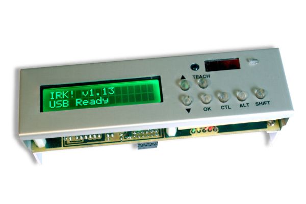
IRK! is a USB keyboard, without keys, that you can operate just by using your LEARNINGinfrared remote control.I created it to allow me to control my MythTV home theater PC with my LEARNING infrared remote control instead of having to use a real USB keyboard – but it will work with any system (Linux, Windows, or whatever) that you can plug a USB keyboard into, and also other home theater systems like XBMC and MediaPortal.Many people use LIRC on Linux to control MythTV, but my solution does not require you to edit any complicated configuration files and does not need any special device drivers or software to be installed.IRK! is an open-hardware project that I created on SourceForge. Contributors and bug reports are welcome.Features
The feature set so far includes:
- IRK! teaches your LEARNING remote control IR codes
- IRK! lets you map IR codes to USB keystrokes – for example, Shift+Enter
- IRK! sends the USB keystroke to your PC when you press a button on your remote
- IRK! can send power off, sleep, and wake codes to your PC
- IRK! devices can have one of 256 addresses – so you can have multiple IRK!’s
- IRK! handles broadcasts – so multiple IRK!’s can respond to a single remote button
- IRK! supports USB Consumer Device functions (e.g. Mute)
- IRK! has a programmable LCD backlight delay (or ON/OFF commands)
Prerequisites
This project is for reasonably advanced electronic nuts…but if you stick with it anyone can make it.
You’re going to be making a Printed Circuit Board (PCB) or at least a matrix board, soldering electronic components onto it, and then programming a PIC micro-controller, so you’ll need:
- PCB making equipment. I use inkjet transparencies, an ordinary fluorescent desk lamp as a UV source, and Kinsten positive-acting presensitised board, and ferric chloride etchant.
- A good soldering iron with a fine tip.
- A micro-controller programmer able to program a Microchip PIC18F2550 micro-controller, such as a Pickit2 or you can make your own (search for “pic programmer” on Instructables).
And in case it doesn’t work for you first time, you may find it helpful to have:
- A good logic analyser like Logic (works on Windows or Linux)
- A USB trace capture program like USBTrace (Windows) or Wireshark (free on Linux). On Linux, make sure you’re using the libpcap 1.1 (packet capture library) or later.
Step 2: Circuit Diagram
The infrared receiver consists of the TSOP4838 IR receiver module. Its job is to convert 38 kHz modulated IR signals from your remote control into digital ones and zeroes. The receiver will output a logical one (0V) when the remote is transmitting a 38 kHz signal, and will output a logical zero (+5V) during periods of silence.Infrared Transmitter Interface
The transmitter consists of a PN2222A transistor (but any general purpose NPN transistor will work) which drives a series of three Infrared Light Emitting Diodes (IR LEDs). Driving three IR LEDs is done to boost the transmitting power. Learning remotes are designed to accept signals from remote controls in close proximity and remotes are designed to produce an intense IR signal. Consequently, IRK! must produce a fairly intense IR signal in order for the learning remote to be able to “see” it during the learning process.LCD Interface
The Liquid Crystal Display is a 2×16 (2 lines at 16 characters per line) unit compatible with the Hitachi HD44780 4-bit defacto standard. You can use a 4×16, or a 4×20 display if you like as long as it is HD44780-compatible. These are available on eBay at very reasonable prices.USB Interface
The USB interface is provided by the USB module built into the PIC18F2550 microcontroller. It is managed programmatically by the USB library provided with the MikroC Pro C Compiler.Activity LED Interface
Hardly an interface as such – a simple LED and a current-limiting resistor – but if you use a high intensity (8000 mcd) green LED then I’ve found that you can make the resistor an insanely high value – like about 18 kΩ – and the LED is still bright! That means that the driving current is only 100 uA. If you use the original 470Ω resistor specified in the circuit diagram then you could end up being startled by the brightness.
Power Interface (experimental)
The circuit diagram shows how to power the IRK! unit using the standby voltage (Vsb) output from your PC’s power supply. However, this has not been tested. You can leave the connection to Vsb out and IRK! will still work – but if you power down your system, you will not be able to power it up using your remote control. Just walk over to your PC and turn it on the old fashioned way!
Parts

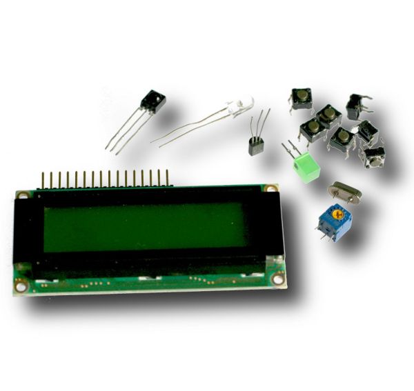
Major PartsCapacitors
2 x 4.7uF Tag Tantalum capacitor (polarised)
2 x 22pF Ceramic capacitor
1 x 220nF Tag Tantalum capacitor (polarised)
1 x 100nF Ceramic capacitor (SMD 1206 sized package)Connectors/Headers
1 x Female header 16-pin SIL (for the LCD)
1 x Male header 2×4-pin (for the PWR/RST leads)
1 x Male header 1×6-pin (for the ICSP)
1 x Male header 2×5-pin (for the USB cable)
1 x Male header 1×2-pin (for the Standby voltage lead)Diodes
3 x 1N5817-B Schottky barrier diode (D041 package)
Integrated Circuits
1 x PIC18F2550 Microchip 18F2550 microcontroller (28-pin DIP)
1 x TSOP4838 IR Receiver and Demodulator
Liquid Crystal Display
1 x HD44780-compatible LCD Display (16×2) with backlight
Light Emitting Diodes
1 x General purpose 5 mm LED (any color)
3 x TSAL7400 Infrared LED (940 nm)
Transistors
1 x PN2222A General purpose NPN Transistor (TO92 package) (or equivalent e.g. BC548)
2 x 2N7000 General purpose N-Channel MOSFET (TO92 package)
1 x BC557B General purpose PNP Transistor (TO92 package) (or equivalent e.g. PN2907)
Resistors
1 x 100 kΩ 1/4 Watt Resistor
1 x 100 Ω 1/4 Watt Resistor
1 x 470 Ω 1/4 Watt Resistor
1 x 22 Ω 1/4 Watt Resistor
1 x 4.7 kΩ 1/4 Watt Resistor
2 x 10k Ω 1/4 Watt Resistor
1 x 4.7 kΩ 1/4 Watt Resistor
1 x 10 kΩ 1/4 Watt Resistor
Switches
7 x Tactile microswitches SPST-NO momentary action (Omron B3F series or similar)
Variable Resistors
1 x 10 kΩ Variable trimmer resistor (Bourns 3362 series or similar)
Crystals
1 x 8 MHz Crystal (HC49/S package)
Miscellaneous Parts
– Female rectangular plugs (Harwin M20-106 series) for connecting reset/power switches to the motherboard (you can usually harvest these from an old PC)
– A 5.25″ drive bay box/panel (or a standalone box) to house the assembled PCB
– Miscellaneous mounting hardware (nuts, bolts, spacers etc)
Circuit Board Making Supplies
– Kinsten double-sided PCB (preferrably fibreglass)
– Kinsten DP50 developer
– Ferric Choride etchant (or whatever you normally use)

