Summary of RC snubber calculator spreadsheet
RC Snubber Calculator Spreadsheet simplifies selecting RC snubber components to damp parasitic RLC oscillations in power switching circuits. Users measure the original oscillation frequency, add a known test capacitor and measure the shifted frequency, then choose a damping factor. The spreadsheet computes recommended R and C, estimates parasitic capacitance and inductance, and estimates resistor dissipation using supply voltage and switching frequency. It also includes a table of standard E-series values and a damping-factor response graph to guide component selection.
Parts used in the RC Snubber Calculator Spreadsheet:
- Test film capacitor (CTEST)
- Snubber capacitor (C)
- Snubber resistor (R)
- MOSFET (test subject on PCB)
- Oscilloscope (for frequency measurements)
- PCB parasitic inductance (LP) and capacitance (CP) as modeled components
RC Snubber Calculator Spreadsheet
In power switching applications, a designer often has to contend with spurious oscillations. These are the result of parasitic capacitance and inductance on the board and behave like the step response of an RLC circuit. These transients can induced undesired noise in neighboring circuits and create over voltage spikes that can compromise long term component reliability.The most common way to mitigate the effects of these transients is by using an RC snubber circuit. There are many excellent sources on the web discussing this topic so I won’t repeat the discussion here (see references at the end for more information). Instead, I’m offering an Excel-based calculator that simplifies the components selection should you be faced with this task.
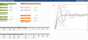
On the left side, colored in green, is the “inputs” section. In order to precisely “tune” the RC snubber, you should measure the frequency of the oscillations (without having the snubber) using an oscilloscope and enter it under fRING.
The next step is to add a know value test film capacitor in parallel with the MOSFET (CTEST) and measure the new oscillating frequency as a result. Finally, you must select the damping factor for the desired response depending on how much overshoot you can tolerate. There’s a graph in this document illustrating the normalized effect of the damping factor on the response.
The “results” section of the spreadsheet (colored orange) automatically calculate the recommended R and C values. The estimated parasitic capacitance CP and inductance LP are also displayed for reference. Power dissipated in the Rs resistor is also estimated using the maximum supply voltage (VS) and the maximum switching frequency (fS) so you can select a resistor with the appropriate power handling capability.
A table with standard E-series values is included for convenience.
For more detail: RC snubber calculator spreadsheet
- How do I determine the oscillation frequency to use in the spreadsheet?
Measure the oscillation frequency without the snubber using an oscilloscope and enter it as fRING. - How is the test capacitor used in the tuning process?
Add a known value test film capacitor in parallel with the MOSFET (CTEST) and measure the new oscillating frequency to enter in the spreadsheet. - What input controls how damped the snubber response will be?
Select the desired damping factor based on acceptable overshoot; the spreadsheet includes a graph showing normalized damping effects. - What outputs does the spreadsheet provide after inputs are entered?
The results section calculates recommended R and C values, estimates parasitic CP and LP, and estimates power dissipated in R. - How is resistor power dissipation estimated?
Power in the snubber resistor is estimated using the maximum supply voltage VS and maximum switching frequency fS provided in the spreadsheet. - Does the spreadsheet help choose standard component values?
Yes, a table with standard E-series values is included for convenience. - Why measure frequency without the snubber first?
Measuring the un-snubbed frequency (fRING) gives the baseline oscillation to accurately tune the snubber. - What components are being modeled as parasitics in the spreadsheet?
The spreadsheet estimates parasitic capacitance CP and inductance LP as part of the RLC behavior.