
Summary of IR(infrared) Remote Control Relay Board with PIC 12F675 Microcontroller
This article explains how to control home appliances using an old NEC protocol-based remote with a PIC 12F675 microcontroller. It details the NEC protocol structure, bit timing, repeat codes, and decoding methods using interrupts.
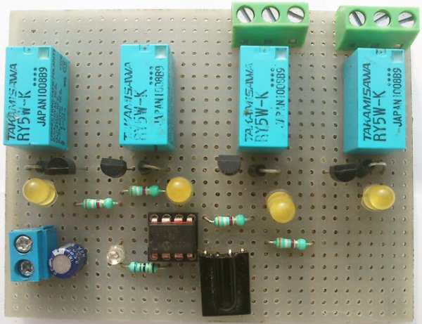
Parts used in IR Remote Control Relay Board:
- NEC IR protocol based TV, DVD or VCR remote control
- PIC 12F675 Microcontroller
- IR sensor
- Relay board
- Home appliances (fan, bulb)
- Decoupling capacitor 100nF
- Decoupling capacitor 10uF
Introduction
This little project will demonstrate how you can use your old NEC IR protocol based TV,DVD or VCR remote control to control you home appliances like fan bulb or virtually anything.
There are a number of consumer Infrared protocols out there and they have been used for every single purpose possible i guess, like PDA laptops and other consumer appliances. RC-5 & RC-6 by Phillips , RCA are few examples of consumer IR protocols

- A 9ms leading pulse burst (16 times the pulse burst length used for a logical data bit)
- A 4.5ms space
- The 8-bit address for the receiving device
- The 8-bit logical inverse of the address
- The 8-bit command
- The 8-bit logical inverse of the command
- Final 562.5µs pulse burst to show end of message transmission.
- Logical ‘0’ – a 562.5µs pulse burst followed by a 562.5µs space, with a total transmit time of 1.125ms
- Logical ‘1’ – a 562.5µs pulse burst followed by a 1.6875ms space, with a total transmit time of 2.25


because (address + address inverse) or (command+command inverse) will always contain 8 ‘0’s and 8 ‘1’s so (8 * 1.125ms) + (8 * 2.25ms) == 27 ms .
according to this total time required to transmit the frame is (9ms +4.5ms +27ms+27ms) = 67.5 ms.

T1 leading pulse at 84.115ms
T2 space on 93.28ms
T3 Address starts at 97.580ms
T4 Address ends , address inverse starts 107.670ms
T5 address inverse ends , command starts at 124.486ms
T6 Command ends, command inverse starts 135.696ms
T7 Command inverse ends and last 562.5µs pulse to show end of transmission

Extended NEC protocol (not used in this demonstration)
Repeat Codes
If the key on the remote controller is kept depressed, a repeat code will be issued, typically around 40ms after the pulse burst that signified the end of the message. A repeat code will continue to be sent out at 108ms intervals, until the key is finally released. The repeat code consists of the following, in order:
A 9ms leading pulse burst
A 2.25ms space
A 562.5µs pulse burst to mark the end of the space (and hence end of the transmitted repeat code).
the figures give blow show the timing of repeat codes


Decoding NEC is really easy ,there are certainly various methods to do, some examples i have see n used polling method in which the firmware keep polling the input pin of microcontroller which connects to IR sensor , other method is to user interrupt ,in this demonstration we will be using the interrupt method as this one is better, we will be using interrupt on change.
Schematic :
Because of power supply , Decoupling capacitor 100nF and 10uF is recommended on pin 1 and GND , as point out by readers.


Source : IR(infrared) Remote Control Relay Board with PIC 12F675 Microcontroller
- What is the main purpose of this project?
The project demonstrates using an old NEC IR protocol based remote to control home appliances like fans or bulbs. - Which infrared protocol is used in this demonstration?
The demonstration sticks to the NEC protocol by NEC corporation. - How is the NEC protocol decoded in this project?
The project uses the interrupt on change method for decoding rather than polling. - What are the recommended decoupling capacitors for the schematic?
A 100nF and a 10uF capacitor are recommended on pin 1 and GND due to power supply requirements. - How long does it take to transmit the full NEC frame?
The total time required to transmit the frame is 67.5 ms. - What happens if a key on the remote is kept depressed?
A repeat code is issued typically around 40ms after the message end and continues at 108ms intervals until released. - How many bits are sent in least significant bit first order?
Four bytes of data bits are sent in least significant bit first order. - Can the address range be extended in the NEC protocol?
Yes, the address range can be extended from 256 values to approximately 65000 values in the extended protocol.
