Summary of Interfacing PIR Sensor with PIC Microcontroller
This article details a project to interface a PIR motion sensor with a PIC16F877A microcontroller. When the sensor detects moving objects emitting infrared radiation, it triggers a buzzer. The system uses MPLABX IDE and XC8 compiler for programming via a PICkit 3 programmer. The logic monitors the PIR output pin; if high, the buzzer activates for one second before turning off. Sensitivity and duration are adjustable via potentiometers on the sensor module.
Parts used in the Interfacing PIR Sensor with PIC Microcontroller:
- PicKit 3
- PIR Sensor
- PIC16F877A IC
- 40 - Pin IC holder
- Perf board
- 20 MHz Crystal OSC
- Female and Male Bergstick pins
- 33pf Capacitor - 2Nos, 100uf and 10uf cap.
- 680 ohm, 10K and 560ohm Resistor
- LED of any color
- Soldering kit
- IC 7805
- 12V Adapter
- Buzzer
- Connecting wires
- Breadboard
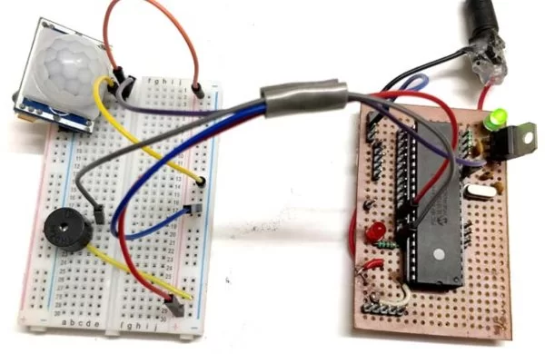
Today we are simple going to interface PIR with PIC Microcontroller PIC16F877A. In this circuit if some moving objects comes in the range of PIR sensor, the buzzer will start beeping.
Material Required
- PicKit 3
- PIR Sensor.
- PIC16F877A IC
- 40 – Pin IC holder
- Perf board
- 20 MHz Crystal OSC
- Female and Male Bergstick pins
- 33pf Capacitor – 2Nos, 100uf and 10uf cap.
- 680 ohm, 10K and 560ohm Resistor
- LED of any color
- 1 Soldering kit
- IC 7805
- 12V Adapter
- Buzzer
- Connecting wires
- Breadboard
PIR Sensor:
PIR sensor is inexpensive, low-power and easy to use Motion Detections Sesnor. PIR sensor only receives infrared rays, not emits that’s why it’s called passive. PIR sense any change in heat, and if there is a change it gives HIGH at OUTPUT. PIR Sensor also referred as Pyroelectric or IR motion sensor.
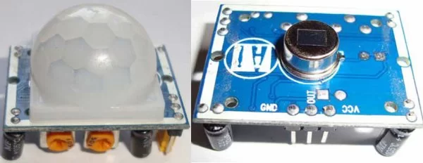
Every object emits some amount of infrared when heated, similar to that human body emits IR due to body heat. Infrared created by every object because of the friction between air and object. The main component of PIR sensor is Pyroelectric sensor. Along with this, BISS0001 (“Micro Power PIR Motion Detector IC”), some resistors, capacitors and other components used to build PIR sensor. BISS0001 IC take the input from sensor and does processing to make the output pin HIGH or LOW accordingly.
You can also adjust distance sensitivity and time duration for which the output pin will be high once motion is detected. It has two potentiometer knobs to adjust these two parameters.
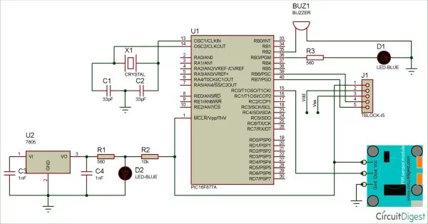
Circuit Diagram
PIC Microcontroller:
In order to program the PIC microcontroller for interfacing PIR, we will need an IDE (Integrated Development Environment), where the programming takes place. A compiler, where our program gets converted into MCU readable form called HEX files. An IPE (Integrated Programming Environment), which is used to dump our hex file into our PIC MCUs.
IDE: MPLABX v3.35
IPE: MPLAB IPE v3.35
Compiler: XC8
Microchip has given all these three software for free. They can be downloaded directly from their official page. I have also provided the link for your convenience. Once downloaded install them on your computer. If you have any problem doing so you can view the Video given at the end.
To dump or upload our code into PIC, we will need PICkit 3. The PICkit 3 programmer/debugger is a simple, low-cost in-circuit debugger that is controlled by a PC running MPLAB IDE (v8.20 or greater) software on a Windows platform. The PICkit 3 programmer/debugger is an integral part of the development engineer’s tool suite. In addition to this we will also need other hardware like Perf board, Soldering station, PIC ICs, Crystal oscillators, capacitors etc. But we will add them to our list as we progress through our tutorials.
We will be programming our PIC16F877A using the ICSP option that is available in our MCU.
To burn the code, follow below steps:
- Launch the MPLAB IPE.
- Connect one end of your PicKit 3 to your PC and other end to your ICSP pins on perf board.
- Connect to your PIC device by clicking on the connect button.
- Browse for the Blink HEX file and click on Program.
Code and Explanation
First, we need to set the configuration bits in the pic microcontroller and then start with void main function.
In the below code, ‘XC.h’ is the header file that contain all the friendly names for the pins and peripherals. Also we have defined crystal oscillator frequency, PIR and Buzzer pins connection in below code.
#include <xc.h>
#define _XTAL_FREQ 20000000 //Specify the XTAL crystall FREQ
#define PIR RC0
#define Buzzer RB2
In the void main (), ‘TRISB=0X00’ is used to instruct the MCU that the PORTB pins are used as OUTPUT, ‘TRISC=0Xff’ is used to instruct the MCU that the PORTB pins are used as INPUT. And ‘PORTB=0X00’ is used to instruct the MCU to make all the OUTPUT of RB3 Low.
TRISB=0X00;
TRISC=0Xff;
PORTB=0X00; //Make all output of RB3 LOW
As per the below code, whenever PIR get HIGH the buzzer will get HIGH or else it remain OFF.
while(1) //Get into the Infinie While loop
{
    if(PIR ==1){
        Buzzer=1;
       __delay_ms(1000);   //Wait
    }
    else{
        Buzzer=0;
    }
  }
}
Complete Code with a Demo Video is given at the end of this project.
Working of PIR Sensor with PIC Microcontroller:
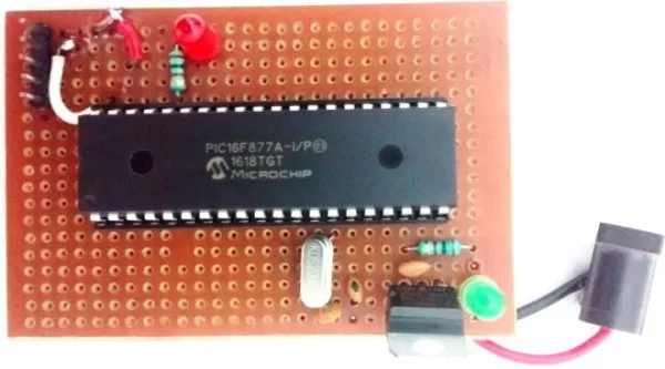
This project does not have any complicated hardware setup, we are again using the same PIC Microcontroller board(as shown below) which we have created in LED blinking Tutorial. Simply connect the PIR Sensor Module with your PIC Microcontroller board according to the connection diagram. Once you are done with the connections, simply dump the code using your PicKit 3 programmer as explained in previous tutorial and enjoy your output.
After uploading the program, PIR sensor is ready to give OUTPUT. Whenever, a human being or object that emits IR comes in the range of PIR it gives HIGH to the OUTPUT. And, based on that output the buzzer will operate. If PIR output is high buzzer input gets high and vice versa.

You can control the distance of sensing and time delay by using two potentiometers fixed on the PIR module.
// ‘C’ source line config statements
// CONFIG
#pragma config FOSC = HS // Oscillator Selection bits (HS oscillator)
#pragma config WDTE = OFF // Watchdog Timer Enable bit (WDT disabled)
#pragma config PWRTE = OFF // Power-up Timer Enable bit (PWRT disabled)
#pragma config BOREN = ON // Brown-out Reset Enable bit (BOR enabled)
#pragma config LVP = OFF // Low-Voltage (Single-Supply) In-Circuit Serial Programming Enable bit (RB3 is digital I/O, HV on MCLR must be used for programming)
#pragma config CPD = OFF // Data EEPROM Memory Code Protection bit (Data EEPROM code protection off)
#pragma config WRT = OFF // Flash Program Memory Write Enable bits (Write protection off; all program memory may be written to by EECON control)
#pragma config CP = OFF // Flash Program Memory Code Protection bit (Code protection off)
// #pragma config statements should precede project file includes.
// Use project enums instead of #define for ON and OFF.
#include <xc.h>
#define _XTAL_FREQ 20000000 //Specify the XTAL crystall FREQ
#define PIR RC0
#define Buzzer RB2
void main() //The main function
{
TRISB=0X00; //Instruct the MCU that the PORTB pins are used as Output.
TRISC=0Xff; //Instruct the MCU that the PORTB pins are used as Input.
PORTB=0X00; //Make all output of RB3 LOW
while(1) //Get into the Infinie While loop
{
if(PIR ==1){
Buzzer=1;
__delay_ms(1000); //Wait
}
else{
Buzzer=0;
}
}
}
Read more detail:Interfacing PIR Sensor with PIC Microcontroller
- How do I program the PIC microcontroller for this project?
You must use MPLABX v3.35 as the IDE, XC8 as the compiler, and MPLAB IPE v3.35 to upload the HEX file using a PicKit 3 programmer. - What happens when the PIR sensor detects motion?
The sensor outputs a HIGH signal, which causes the connected buzzer to beep or turn on. - Why is the sensor called passive?
It is called passive because it only receives infrared rays emitted by objects rather than emitting them itself. - Can I adjust the sensing range and time delay?
Yes, you can control the distance of sensing and time delay using the two potentiometer knobs fixed on the PIR module. - Which pins are configured as input and output in the code?
PORTC is set as input (TRISC=0Xff) for the PIR sensor, while PORTB is set as output (TRISB=0X00) for the buzzer. - What frequency is specified for the crystal oscillator in the code?
The code defines the crystal frequency as 20000000 Hz (20 MHz) using the _XTAL_FREQ directive. - How long does the buzzer stay on after motion is detected?
The buzzer stays on for 1000 milliseconds (one second) due to the __delay_ms(1000) command in the loop. - What software tools are required to dump the code into the MCU?
You need the MPLAB IPE software running on a PC along with the PicKit 3 hardware debugger.