Summary of Interfacing Graphical LCD(GLCD-JHD12864E) with Microchip PIC16f877 Microcontroller
This tutorial demonstrates interfacing a JHD12864E graphical LCD with a Microchip PIC16F877 microcontroller using C code in MPLAB-IDE. The project displays the website name "www.microcontroller-project.com" and a custom thick-line pattern on the 128x64 dot matrix display. The author explains pin configurations, initialization commands, and contrast adjustment via a potentiometer. The provided code initializes the LCD, clears the screen, and sends specific data bytes to render characters across two controller halves.
Parts used in Interfacing Graphical LCD with PIC16F877:
- Microchip Pic16f877 Microcontroller
- JHD12864E Graphical LCD
- 20MHZ Crystal
- 30pf Capacitors
- Variable Resistor Potentiometer (0-100k)
- Connecting Wires
- Battery or Adapter Power Source
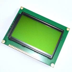
In this post/tutorial i am going to teach you how to interface graphical lcd jhd12864E with microchip pic16f877 microcontroller. I am going to display my website name “www.microcontroller-project.com” and a special pattern that displays thick lines on dotted graphical lcd display. In graphical lcd name “jhd12864” the number 128×64 means lcd has 128 coulombs and 64 rows. On graphical lcd’s data(character, numbers) is displayed on dots. A joint between coulomb and row is termed as dot. Total dots present in jhd12864 lcd are 128 x 64 = 8192 dots. When dots are combined they make a dot cluster. This cluster of dots in square form is know as matrix. On these 8192 dots we can display/make our data(character, number, image). In graphical lcd’s we are free to make character’s of our desired size unless the size is in the matrix of graphical lcd.
Before proceeding i would recommend you to please go through a small tutorial. This tutorial will helps you to understand how text is displayed on graphical lcd, how graphical lcd dots are arranged in pages, how graphical lcd is initialized(Graphical Lcd initializing commands), each and every pin of graphical lcd is deeply explained in the tutorial. You can easily understand the code below if you go through the tutorial.
Graphical Lcd with Pic Microcontroller – Project requirements
- Microcontroller(Microchip Pic16f877)
- Graphical Lcd(JHD12864E)
- Crystal (20MHZ)
- Capacitors (30pf)
- Potentiometer-Variable resistor(0-100k)
- Connecting Wires
- Power Source (Battery, Adapter etc)
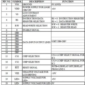
Graphical Lcd which i am using is JHD12864E. It comes in 20 Pin Package. Pin out of JHD12864E is given below. Its an 8-bit lcd. It comes with two built in controllers. Each controller is selected with chip select pins (cs1 and cs2). Visit the tutorial link given above to properly understand the pin functions and how to use them properly.
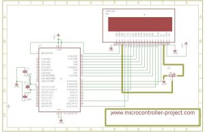
Graphical lcd with pic microcontroller – Project Circuit Diagram
All other connections are necessary connections to make controller work. Attach crystal(20Mhz) to controller in parallel to two 30pf capacitors. Supply +5v to vcc and vdd. Make GND ground. Circuit diagram of the project is give below.
- Clearlcd() function is half-filling each page with dots. Both halfs pages are filled in up and down position. If 2nd page of 1rst half is filled from down then 2nd page of 2nd half is filled from up.
- #define statements are defining pins as rs,rw,en etc. Now these pins can be accessed in code as rs,rw,en etc.
- delay() function is used to generate some delay where required.
- lcdcmd() is sending commands to lcd. It also manipulates lcd pins to successfully execute the command.
- lcddata() is sending data to lcd. It also manipulates lcd pins to successfully display data on lcd.
Main() function contains the code that displays all stuff on lcd. First it jumps to clearLcd() function fills pages with dots. Then it displays my web site name on lcd. Pattern of each character of my site is commented in the code.
| #include<htc.h> | |
| void clearlcd(); | |
| #define rs RD7 | |
| #define rw RD6 | |
| #define en RD5 | |
| #define cs1 RD4 | |
| #define cs2 RC4 | |
| #define re RD2 | |
| void delay(unsigned int d){ | |
| unsigned int i,j; | |
| for(i=0;i< d;i++) | |
| for(j=0;j< 5;j++); | |
| } | |
| void lcdcmd(char value){ | |
| PORTB=value; | |
| rw=0; | |
| rs=0; | |
| en=0; | |
| delay(300); | |
| en=1; | |
| delay(300); | |
| en=0; | |
| } | |
| lcddata(char data1) | |
| { | |
| PORTB=data1; | |
| rw=0; | |
| rs=1; | |
| en=0; | |
| delay(300); | |
| en=1; | |
| delay(300); | |
| en=0; | |
| } | |
| void main(){ | |
| TRISB=0x00; //Port-B as Output Port | |
| TRISD=0x00; //Port-D as Output Port | |
| TRISD=0x00; //Port-D as Output Port | |
| TRISC=0x00; //Port-C as Output Port | |
| delay(300); | |
| re=1; //Reset disabled | |
| lcdcmd(0x3E); //Display Off | |
| lcdcmd(0x3F); //Display on | |
| lcdcmd(0x3F); //Display on | |
| clearlcd(); | |
| cs1=1; //Selecting 1 Half | |
| cs2=0; //Switch off other half | |
| lcdcmd(0x3F); //Display on | |
| lcdcmd(0x40); //Setting y-address | |
| lcdcmd(0xBB); //Setting x-address page 3 is selected | |
| lcdcmd(0xC0); //start line | |
| delay(3000); | |
| lcddata(0x00); //M | |
| lcddata(0xFD); | |
| lcddata(0xFB); | |
| lcddata(0xF7); | |
| lcddata(0xFB); | |
| lcddata(0xFD); | |
| lcddata(0x00); | |
| lcddata(0xFF); //M | |
| lcddata(0x0D); //i | |
| lcddata(0xFF); | |
| lcddata(0xC7); //c | |
| lcddata(0xBB); | |
| lcddata(0x7D); | |
| lcddata(0x7D); //c | |
| lcddata(0xFF); | |
| lcddata(0x01); //r | |
| lcddata(0xF7); | |
| lcddata(0xFB); | |
| lcddata(0xFD); //r | |
| lcddata(0xFF); | |
| lcddata(0xC3); //o | |
| lcddata(0x3D); | |
| lcddata(0x3D); | |
| lcddata(0xC3); //o | |
| lcddata(0xFF); | |
| lcddata(0xC7); //c | |
| lcddata(0xBB); | |
| lcddata(0x7D); | |
| lcddata(0x7D); //c | |
| lcddata(0xFF); | |
| lcddata(0xC3); //o | |
| lcddata(0x3D); | |
| lcddata(0x3D); | |
| lcddata(0xC3); //o | |
| lcddata(0xFF); | |
| lcddata(0x01); //n | |
| lcddata(0xF7); | |
| lcddata(0xF7); | |
| lcddata(0x07); //n | |
| lcddata(0xFF); | |
| lcddata(0xF7); //t | |
| lcddata(0x01); | |
| lcddata(0x67); | |
| lcddata(0x7F); //t | |
| lcddata(0xFF); | |
| lcddata(0x01); //r | |
| lcddata(0xF7); | |
| lcddata(0xFB); | |
| lcddata(0xFD); //r | |
| lcddata(0xFF); | |
| lcddata(0xC3); //o | |
| lcddata(0x3D); | |
| lcddata(0x3D); | |
| lcddata(0xC3); //o | |
| lcddata(0xFF); | |
| lcddata(0x01); //l | |
| lcddata(0x01); | |
| lcddata(0xFF); //l | |
| lcddata(0x01); //l | |
| lcddata(0x01); | |
| lcddata(0xFF); //l | |
| lcddata(0xC7); //e | |
| lcddata(0xAB); | |
| lcddata(0x75); | |
| cs1=0; //Switch off First Half | |
| cs2=1; //Selecting 2nd Half | |
| lcdcmd(0x3F); //Display on | |
| lcdcmd(0x40); //Setting y-address | |
| lcdcmd(0xBB); //Setting x-address page 3 is selected | |
| //lcdcmd(0xC0); //start line | |
| lcddata(0x79); //e | |
| lcddata(0xFF); | |
| lcddata(0x01); //r | |
| lcddata(0xF7); | |
| lcddata(0xFB); | |
| lcddata(0xFD); //r | |
| lcddata(0xFF); | |
| lcddata(0xF7); //- | |
| lcddata(0xF7); | |
| lcddata(0xF7); //- | |
| lcddata(0xFF); | |
| lcddata(0x01); //p | |
| lcddata(0xED); | |
| lcddata(0xED); | |
| lcddata(0xF3); //p | |
| lcddata(0xFF); | |
| lcddata(0x01); //r | |
| lcddata(0xF7); | |
| lcddata(0xFB); | |
| lcddata(0xFD); //r | |
| lcddata(0xFF); | |
| lcddata(0xC3); //o | |
| lcddata(0x3D); | |
| lcddata(0x3D); | |
| lcddata(0xC3); //o | |
| lcddata(0xFF); | |
| lcddata(0xBF); //j | |
| lcddata(0x7F); | |
| lcddata(0x05); //j | |
| lcddata(0xFF); | |
| lcddata(0xC7); //e | |
| lcddata(0xAB); | |
| lcddata(0x75); | |
| lcddata(0x79); //e | |
| lcddata(0xFF); | |
| lcddata(0xC7); //c | |
| lcddata(0xBB); | |
| lcddata(0x7D); | |
| lcddata(0x7D); //c | |
| lcddata(0xFF); | |
| lcddata(0xF7); //t | |
| lcddata(0x01); | |
| lcddata(0x67); | |
| lcddata(0x7F); //t | |
| lcddata(0xFF); | |
| lcddata(0x9F); //. | |
| lcddata(0x9F); //. | |
| lcddata(0xFF); | |
| lcddata(0xC7); //c | |
| lcddata(0xBB); | |
| lcddata(0x7D); | |
| lcddata(0x7D); //c | |
| lcddata(0xFF); | |
| lcddata(0xC3); //o | |
| lcddata(0x3D); | |
| lcddata(0x3D); | |
| lcddata(0xC3); //o | |
| lcddata(0xFF); | |
| lcddata(0x01); //m | |
| lcddata(0xFD); | |
| lcddata(0x01); | |
| lcddata(0xFD); | |
| lcddata(0x01); //m | |
| lcddata(0xFF); | |
| //while(1); //After Printing name remain here for ever…… | |
| } | |
| void clearlcd() | |
| { | |
| unsigned int i=0,j,k; | |
| int page[]={0xB8,0xB9,0xBA,0xBB,0xBC,0xBD,0xBE,0xBF}; | |
| cs1=1; //First Half is selected | |
| cs2=0; //Second Half unselected | |
| lcdcmd(0xC0); //Start line, (64 rows) selects from where to start(1 line) | |
| while(i!=8){ | |
| cs2=0; //Second Half unselected | |
| cs1=1; //First Half is selected | |
| lcdcmd(page[i]); //Setting x-address, page is selected | |
| lcdcmd(0x40); //Setting y-address, coulomb of page is selected | |
| for(j=1;j<=65;j++){ | |
| if(j<=64){ | |
| lcddata(0xF0); | |
| } | |
| else if(j==65){ | |
| cs2=1; //Second Half Selected | |
| cs1=0; //First Half unselected | |
| lcdcmd(page[i]); //Setting x-address, page is selected | |
| lcdcmd(0x40); //Setting y-address, coulomb of page is selected | |
| for(k=0;k<=63;k++) | |
| lcddata(0x0F); | |
| } | |
| } | |
| i=i+1; | |
| } | |
| } |
- What does the number 128×64 represent in the JHD12864 LCD?
It means the LCD has 128 columns and 64 rows, totaling 8192 dots. - How is the LCD contrast adjusted in this project?
A variable resistor connected between pins VEE and V0 is used to set the contrast by rotating the knob. - Which ports of the PIC16F877 are used for the LCD connections?
LCD data pins connect to Port-B, while control pins like RS, RW, EN, CS1, RST connect to Port-D, and CS2 connects to Port-C. - How many controllers are built into the JHD12864E LCD?
The LCD comes with two built-in controllers selected by chip select pins CS1 and CS2. - What compiler and IDE were used to write the code?
The code was written in C++ language using MPLAB-IDE with the High Tech C compiler. - How are the two halves of the LCD screen managed in the code?
The code uses CS1 and CS2 pins to select either the first half or the second half of the display sequentially. - What function is used to fill the pages with dots before displaying text?
The clearlcd() function is used to fill each page with dots in up and down positions. - Why is the delay function necessary in the code?
The delay function generates required wait times for the LCD to process commands and data successfully.