Summary of Interfacing GPS Module with PIC Microcontroller
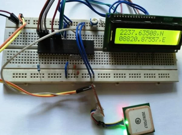
This article details interfacing a uBlox-G7020 GPS module with a PIC16F877A microcontroller to extract and display real-time latitude and longitude data on a 16x2 LCD. The system utilizes the USART communication protocol at 9600 baud rate to parse NMEA sentences, specifically the $GPGGA string, filtering out time and other data to isolate coordinates. A 20MHz crystal provides the necessary clock frequency, while a potentiometer adjusts LCD contrast for clear visibility of the location information.
Parts used in Interfacing GPS with PIC Microcontroller:
- PIC16F877A Microcontroller (PDIP40 package)
- uBLOX-G7020 GPS Module
- JHD162A 16x2 Character LCD
- Breadboard
- Pickit-3 Programmer
- 5V Adapter
- 20MHz Crystal Oscillator
- Two 33pF Ceramic Capacitors
- 10k Potentiometer
- 4.7k Resistors
- Connecting Wires
GPS is the short-form of Global Positioning System. It is a system which provide accurate Altitude, Latitude, Longitude, UTC time and many more information, which are taken from 2, 3, 4 or more satellite. To read data from GPS, we need some Microcontroller and we already interfaced GPS with Arduino and with Raspberry Pi.
We have selected G7020 GPS module which is made by U-blox. We will receive Longitude and latitude of a particular position from satellite and will display the same on a 16×2 Character LCD. So here we will interface GPS with PIC16F877A microcontroller by microchip.
Components Required:
- Pic16F877A – PDIP40 package
- Bread Board
- Pickit-3
- 5V adapter
- LCD JHD162A
- uBLOX-G7020 GPS module
- Wires to connect peripherals.
- 4.7k Resistors
- 10k pot
- 20mHz Crystal
- 2 pcs 33pF ceramic capacitors
Circuit Diagram and Explanation:-
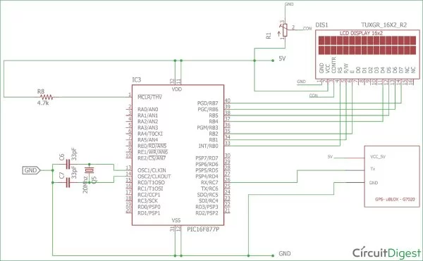
16×2 character LCD is connected across PIC16F877A microcontroller, in which RB0, RB1, RB2 is connected respectively to the LCD pin which is RS, R/W , and E. RB4, RB5, RB6 and RB7 are connected across LCD’s 4 pin D4, D5, D6, D7. The LCD is connected in 4bit mode or nibble mode.
A crystal Oscillator of 20MHz with two ceramic capacitor of 33pF connected across OSC1 and OSC2 pin. It will provide constant 20 MHz clock frequency to the microcontroller.
uBlox-G7020 GPS module, receive and transmit data using UART. PIC16F877A consists one USART driver inside the chip, we will receive data from GPS module by USART, so a cross connection will be made from the microcontroller Rx pin to GPS’s Tx pin and USART Receive pin connected across GPS’s Transmit pin.
The uBlox-G7020 has color code for the pins. The Positive or 5V pin is in Red color, the Negative or GND pin is in Black color and the Transmit pin is in Blue color.
I have connected all this in the breadboard.
Getting Location Data from GPS:
Let’s see how to interface GPS using USART and see the result in a 16×2 character LCD.
The Module will transmit data in multiple strings at 9600 Baud Rate. If we use an UART terminal with 9600 Baud rate, we will see the data received by GPS.
GPS module sends the Real time tracking position data in NMEA format (see the screenshot above). NMEA format consist several sentences, in which four important sentences are given below. More detail about the NMEA sentenceand its data format can be found here.
- $GPGGA: Global Positioning System Fix Data
- $GPGSV: GPS satellites in view
- $GPGSA: GPS DOP and active satellites
- $GPRMC: Recommended minimum specific GPS/Transit data
This is the data received by GPS when connected on 9600 baud rate.
$GPRMC,141848.00,A,2237.63306,N,08820.86316,E,0.553,,100418,,,A*73
$GPVTG,,T,,M,0.553,N,1.024,K,A*27
$GPGGA,141848.00,2237.63306,N,08820.86316,E,1,03,2.56,1.9,M,-54.2,M,,*74
$GPGSA,A,2,06,02,05,,,,,,,,,,2.75,2.56,1.00*02
$GPGSV,1,1,04,02,59,316,30,05,43,188,25,06,44,022,23,25,03,324,*76
$GPGLL,2237.63306,N,08820.86316,E,141848.00,A,A*65
When we use GPS module for tracking any location, we only need coordinates and we can find this in $GPGGA string. Only $GPGGA (Global Positioning System Fix Data) String is mostly used in programs and other strings are ignored.
$GPGGA,141848.00,2237.63306,N,08820.86316,E,1,03,2.56,1.9,M,-54.2,M,,*74
What is the meaning of that line?
Meaning of that line is:-
1. String always starts with a “$” sign
2. GPGGA stands for Global Positioning System Fix Data
3. “,” Comma indicates the separation between two values
4. 141848.00: GMT time as 14(hr):18(min):48(sec):00(ms)
5. 2237.63306,N: Latitude 22(degree) 37(minutes) 63306(sec) North
6. 08820.86316,E: Longitude 088(degree) 20(minutes) 86316(sec) East
7. 1 : Fix Quantity 0= invalid data, 1= valid data, 2=DGPS fix
8. 03 : Number of satellites currently viewed.
9. 1.0: HDOP
10. 2.56,M : Altitude (Height above sea level in meter)
11. 1.9,M : Geoids height
12. *74 : checksum
So we need No. 5 and No.6 to gather information about the module location or, where it is located.
Steps to Interface GPS with PIC Microcontroller:-
- Set the configurations of the microcontroller which include Oscillator configuration.
- Set the Desired port for LCD including TRIS register.
- Connect the GPS module to the microcontroller using USART.
- Initialize the system USART in continuous receive mode, with 9600 baud rate and LCD with 4bit mode.
- Take two character arrays depending on the Length of Latitude and Longitude.
- Receive one character bit at a time and check whether it is started from $ or not.
- If $ Receive then it is a string, we need to check GPGGA, this 5 letters and the comma.
- If it is GPGGA, then we will skip the time, and look for the Latitude and Longitude, We will store the Latitude and Longitude in two character array until N (North) and E (East) not received.
- We will print the array in LCD.
- Clear the array.
Code Explanation:
Let’s look at the code line by line. The first few lines are for setting up configuration bits which were explained in the previous tutorial so I am skipping them for now. The complete Code is given at the end of this tutorial.
These five lines are used for including library header files, lcd.h and eusart.h is for LCD and USART respectively. And xc.h is for microcontroller header file.
#include <xc.h>
#include <stdio.h>
#include <string.h>
#include "supporing_cfile\lcd.h"
#include "supporing_cfile\eusart1.h"
In void main() function, the system_init(); function is used to initialize LCD and USART.
Void main(void) {
    TRISB = 0x00; // Setting as output
    system_init();
The lcd_init(); and EUSART_Intialize(); is called from the two libraries lcd.h and eusart.h
void system_init(void){
    lcd_init(); // This will initialise the lcd
    EUSART1_Initialize(); // This will initialise the Eusart
}
In while loop we break the GPGGA string to get the Longitude and Latitude coordinate. We receiving one bit at a time and compare it with individual characters present in GPGGA string.
We break the codes we will get:-
        incomer_data=EUSART1_Read(); // Check the string '$GPGGA,'
/*------------------------------ Step by step finding the GPGGA line----------------------------*/
        if(incomer_data=='
By using this code we skipping the UTC time.
while (incomer_data != ','){ // skipping GMT Time
                                    incomer_data=EUSART1_Read();
                                }

This code is for storing the Latitude and Longitude data in the character array.
                       incomer_data=EUSART1_Read();
                                latitude[0] = incomer_data;

                                while(incomer_data != ','){
                                for(array_count=1;incomer_data!='N';array_count++){
                                    incomer_data=EUSART1_Read();
                                    latitude[array_count]=incomer_data; // Store the Latitude data
                                    }
                                    incomer_data=EUSART1_Read();

                                    if(incomer_data==','){
                                        for(array_count=0;incomer_data!='E';array_count++){
                                        incomer_data=EUSART1_Read();
                                        longitude[array_count]=incomer_data; // Store the Longitude data
                                        }
                                    }
And finally we have printed longitude and latitude on LCD.
                        array_count=0;
                                    lcd_com(0x80); // LCD line one selection
                                    while(array_count<12){ // Array of Latitude data is 11 digit
                                        lcd_data(latitude[array_count]); // Print the Latitude data
                                        array_count++;
                                        }
                           array_count=0;
                                    lcd_com(0xC0); // Lcd line two selection
                                    while(array_count<13){ // Array of Longitude data is 12 digit
                                        lcd_data(longitude[array_count]); // Print the Longitude data
                                        array_count++;
                                    }
This is how we can interface GPS module with PIC Microcontroller to get the Latitude and longitude of current location.
Complete code and header files are given below.
/*
* File: main.c
* Author: Sourav Gupta
* By:- circuitdigest.com
* Created on April 1, 2018, 2:26 PM
*/
// PIC16F877A Configuration Bit Settings
// ‘C’ source line config statements
// CONFIG
#pragma config FOSC = HS // Oscillator Selection bits (HS oscillator)
#pragma config WDTE = OFF // Watchdog Timer Enable bit (WDT disabled)
#pragma config PWRTE = OFF // Power-up Timer Enable bit (PWRT disabled)
#pragma config BOREN = ON // Brown-out Reset Enable bit (BOR enabled)
#pragma config LVP = OFF // Low-Voltage (Single-Supply) In-Circuit Serial Programming Enable bit (RB3/PGM pin has PGM function; low-voltage programming enabled)
#pragma config CPD = OFF // Data EEPROM Memory Code Protection bit (Data EEPROM code protection off)
#pragma config WRT = OFF // Flash Program Memory Write Enable bits (Write protection off; all program memory may be written to by EECON control)
#pragma config CP = OFF // Flash Program Memory Code Protection bit (Code protection off)
#include <xc.h>
#include <stdio.h>
#include <string.h>
#include “supporing_cfile\lcd.h”
#include “supporing_cfile\eusart1.h”
/*
Hardware related definition
*/
#define _XTAL_FREQ 200000000 //Crystal Frequency, used in delay
/*
Other Specific definition
*/
void system_init(void);
unsigned char incomer_data = 0;
unsigned char longitude[13];
unsigned char latitude[13];
unsigned int array_count=0;
/* Sample line received from the GPS :-
[$GPGGA,100156.000,2690.9416,N,07547.8441,E,1,08,1.0,442.8,M,-42.5,M,,0000*71]1. string always starts with a ?$? sign
2. GPGGA : Global Positioning System Fix Data
3. ?,? Comma indicates the separation between two values
4. 100156.000 : GMT time as 10(hr):01(min):56(sec):000(ms)
5. 2650.9416,N: Latitude 26(degree) 50(minutes) 9416(sec) North
6. 07547.8441,E: Longitude 075(degree) 47(minutes) 8441(sec) East
7. 1 : Fix Quantity 0= invalid data, 1= valid data, 2=DGPS fix
8. 08 : Number of satellites currently viewed.
9. 1.0: HDOP
10. 442.8,M : Altitude (Height above sea level in meter)
11. -42.5,M : Geoids height
12. __ , DGPS data
13. 0000 : DGPS data
14. *71 : checksum
*/
void main(void) {
TRISB = 0x00; // Setting as output
system_init(); // System getting ready and initialising the LCD and USART driver.
//LCD_ScrollMessage(“Circuitdigest.com”);
while(1){
incomer_data=EUSART1_Read(); // Check the string ‘$GPGGA,’
/*—————————— Step by step finding the GPGGA line—————————-*/
if(incomer_data==’$’){ // First statement of the GPS data start with a $ sign
incomer_data=EUSART1_Read(); // If the first if become true then the next phase
if(incomer_data==’G’){
incomer_data=EUSART1_Read();
if(incomer_data==’P’);{
incomer_data=EUSART1_Read();
if(incomer_data==’G’);{
incomer_data=EUSART1_Read();
if(incomer_data==’G’){
incomer_data=EUSART1_Read();
if(incomer_data==’A’){
incomer_data=EUSART1_Read();
if(incomer_data==’,’){ // first , received
incomer_data=EUSART1_Read(); // At this stage Final check in done, GPGGA is found.
while (incomer_data != ‘,’){ // skipping GMT Time
incomer_data=EUSART1_Read();
}
incomer_data=EUSART1_Read();
latitude[0] = incomer_data;
while(incomer_data != ‘,’){
for(array_count=1;incomer_data!=’N’;array_count++){
incomer_data=EUSART1_Read();
latitude[array_count]=incomer_data; // Store the Latitude data
}
incomer_data=EUSART1_Read();
if(incomer_data==’,’){
for(array_count=0;incomer_data!=’E’;array_count++){
incomer_data=EUSART1_Read();
longitude[array_count]=incomer_data; // Store the Longitude data
}
}
array_count=0;
//lcd_com(0x80); // LCD line one selection
while(array_count<12){ // Array of Latitude data is 11 digit
lcd_data(latitude[array_count]); // Print the Latitude data
array_count++;
}
array_count=0;
lcd_com(0xC0); // Lcd line two selection
while(array_count<13){ // Array of Longitude data is 12 digit
lcd_data(longitude[array_count]); // Print the Longitude data
array_count++;
}
//lcd_com(0x01); //clear LCD
}
}
}
}
}
}
}
}
for(array_count=0;array_count<=13;array_count++){
incomer_data=0;
latitude[array_count]=0;
longitude[array_count]=0;
}
array_count = 0;
}
}
/*
This Function is for system initialisations.
*/
void system_init(void){
lcd_init(); // This will initialise the lcd
EUSART1_Initialize(); // This will initialise the Eusart
}
Read more detail:Interfacing GPS Module with PIC Microcontroller
By using this code we skipping the UTC time.
This code is for storing the Latitude and Longitude data in the character array.
And finally we have printed longitude and latitude on LCD.
This is how we can interface GPS module with PIC Microcontroller to get the Latitude and longitude of current location.
Complete code and header files are given below.
/*
* File: main.c
* Author: Sourav Gupta
* By:- circuitdigest.com
* Created on April 1, 2018, 2:26 PM
*/
// PIC16F877A Configuration Bit Settings
// ‘C’ source line config statements
// CONFIG
#pragma config FOSC = HS // Oscillator Selection bits (HS oscillator)
#pragma config WDTE = OFF // Watchdog Timer Enable bit (WDT disabled)
#pragma config PWRTE = OFF // Power-up Timer Enable bit (PWRT disabled)
#pragma config BOREN = ON // Brown-out Reset Enable bit (BOR enabled)
#pragma config LVP = OFF // Low-Voltage (Single-Supply) In-Circuit Serial Programming Enable bit (RB3/PGM pin has PGM function; low-voltage programming enabled)
#pragma config CPD = OFF // Data EEPROM Memory Code Protection bit (Data EEPROM code protection off)
#pragma config WRT = OFF // Flash Program Memory Write Enable bits (Write protection off; all program memory may be written to by EECON control)
#pragma config CP = OFF // Flash Program Memory Code Protection bit (Code protection off)
#include <xc.h>
#include <stdio.h>
#include <string.h>
#include “supporing_cfile\lcd.h”
#include “supporing_cfile\eusart1.h”
/*
Hardware related definition
*/
#define _XTAL_FREQ 200000000 //Crystal Frequency, used in delay
/*
Other Specific definition
*/
void system_init(void);
unsigned char incomer_data = 0;
unsigned char longitude[13];
unsigned char latitude[13];
unsigned int array_count=0;
/* Sample line received from the GPS :-
[$GPGGA,100156.000,2690.9416,N,07547.8441,E,1,08,1.0,442.8,M,-42.5,M,,0000*71]1. string always starts with a ?$? sign
2. GPGGA : Global Positioning System Fix Data
3. ?,? Comma indicates the separation between two values
4. 100156.000 : GMT time as 10(hr):01(min):56(sec):000(ms)
5. 2650.9416,N: Latitude 26(degree) 50(minutes) 9416(sec) North
6. 07547.8441,E: Longitude 075(degree) 47(minutes) 8441(sec) East
7. 1 : Fix Quantity 0= invalid data, 1= valid data, 2=DGPS fix
8. 08 : Number of satellites currently viewed.
9. 1.0: HDOP
10. 442.8,M : Altitude (Height above sea level in meter)
11. -42.5,M : Geoids height
12. __ , DGPS data
13. 0000 : DGPS data
14. *71 : checksum
*/
void main(void) {
TRISB = 0x00; // Setting as output
system_init(); // System getting ready and initialising the LCD and USART driver.
//LCD_ScrollMessage(“Circuitdigest.com”);
while(1){
incomer_data=EUSART1_Read(); // Check the string ‘$GPGGA,’
/*—————————— Step by step finding the GPGGA line—————————-*/
if(incomer_data==’$’){ // First statement of the GPS data start with a $ sign
incomer_data=EUSART1_Read(); // If the first if become true then the next phase
if(incomer_data==’G’){
incomer_data=EUSART1_Read();
if(incomer_data==’P’);{
incomer_data=EUSART1_Read();
if(incomer_data==’G’);{
incomer_data=EUSART1_Read();
if(incomer_data==’G’){
incomer_data=EUSART1_Read();
if(incomer_data==’A’){
incomer_data=EUSART1_Read();
if(incomer_data==’,’){ // first , received
incomer_data=EUSART1_Read(); // At this stage Final check in done, GPGGA is found.
while (incomer_data != ‘,’){ // skipping GMT Time
incomer_data=EUSART1_Read();
}
incomer_data=EUSART1_Read();
latitude[0] = incomer_data;
while(incomer_data != ‘,’){
for(array_count=1;incomer_data!=’N’;array_count++){
incomer_data=EUSART1_Read();
latitude[array_count]=incomer_data; // Store the Latitude data
}
incomer_data=EUSART1_Read();
if(incomer_data==’,’){
for(array_count=0;incomer_data!=’E’;array_count++){
incomer_data=EUSART1_Read();
longitude[array_count]=incomer_data; // Store the Longitude data
}
}
array_count=0;
//lcd_com(0x80); // LCD line one selection
while(array_count<12){ // Array of Latitude data is 11 digit
lcd_data(latitude[array_count]); // Print the Latitude data
array_count++;
}
array_count=0;
lcd_com(0xC0); // Lcd line two selection
while(array_count<13){ // Array of Longitude data is 12 digit
lcd_data(longitude[array_count]); // Print the Longitude data
array_count++;
}
//lcd_com(0x01); //clear LCD
}
}
}
}
}
}
}
}
for(array_count=0;array_count<=13;array_count++){
incomer_data=0;
latitude[array_count]=0;
longitude[array_count]=0;
}
array_count = 0;
}
}
/*
This Function is for system initialisations.
*/
void system_init(void){
lcd_init(); // This will initialise the lcd
EUSART1_Initialize(); // This will initialise the Eusart
}
Read more detail:Interfacing GPS Module with PIC Microcontroller
-
What is the primary function of the G7020 GPS module in this project?
The module receives and transmits data using UART to provide Longitude and Latitude coordinates from satellites. -
How does the microcontroller communicate with the GPS module?
Communication occurs via the internal USART driver using a cross connection between the microcontroller Rx pin and the GPS Tx pin. -
Which specific NMEA sentence is used to retrieve location coordinates?
The $GPGGA (Global Positioning System Fix Data) string is primarily used to gather Latitude and Longitude information. -
At what baud rate does the GPS module transmit data?
The module transmits data strings at a 9600 Baud Rate. -
What components are required to generate the clock frequency for the microcontroller?
A 20MHz crystal oscillator connected with two 33pF ceramic capacitors across OSC1 and OSC2 pins provides the constant clock frequency. -
How is the LCD configured in terms of data transmission mode?
The 16x2 character LCD is connected and operated in 4-bit mode or nibble mode. -
What color codes identify the pins on the uBlox-G7020 module?
Red indicates the Positive 5V pin, Black indicates the Negative GND pin, and Blue indicates the Transmit pin. -
How does the code identify the start of a valid GPS data string?
The code checks if the incoming data starts with a dollar sign ($), followed by the characters G, P, G, G, A, and a comma.