
Summary of Interfacing DC Motor with PIC Microcontroller using L293D
The article explains why microcontrollers cannot drive DC motors directly due to voltage, current, and back-EMF issues, and recommends using H-bridge drivers. It describes L293 and L293D dual H-bridge ICs that drive two motors bidirectionally, provide internal clamp diodes for inductive suppression, accept TTL inputs, and enable drivers in pairs via enable pins. L293D supplies up to 600 mA (4.5–36 V) and L293 up to 1 A.
Parts used in the DC Motor and L293D Project:
- DC Motor
- Microcontroller (operating at +5V or +3.3V)
- L293D IC (dual H-bridge motor driver)
- L293 IC (alternative dual H-bridge motor driver)
- Power supply for motor (e.g., 12V supply)
- Connections/wiring between microcontroller and driver IC
- Enable/input control lines (1,2EN and 3,4EN)
DC Motor and L293D
We can’t drive a DC Motor (depends) directly with a Microcontroller, as DC Motors requires high current and high voltage than a Microcontroller can handle. Microcontrollers usually operates at +5 or +3.3V supply and it I/O pin can provide only up to 25mA current. Commonly used DC Motors requires 12V supply and 300mA current, moreover interfacing DC Motors directly with Microcontrollers may affect the working of Microcontroller due to the Back EMF of the DC Motor. Thus it is clear that, it not a good idea to interface DC Motor directly with Microcontrollers.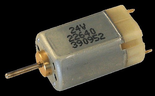
The solution to above problems is to use H-bridge circuit.
It is a special circuit, by using the 4 switches we can control the direction of DC Motor. Depending upon our power requirements we can make our own H-bridge using Transistors/MOSFETs as switches. It is better to use ready made ICs, instead of making our own H-bridge.
L293D and L293 are two such ICs. These are dual H-bridge motor drivers, ie by using one IC we can control two DC Motors in both clock wise and counter clockwise directions. The L293D can provide bidirectional drive currents of up to 600-mA at voltages from 4.5 V to 36 V while L293 can provide up to 1A at same voltages. Both ICs are designed to drive inductive loads such as dc motors, bipolar stepping motors, relays and solenoids as well as other high-current or high-voltage loads in positive-supply applications. 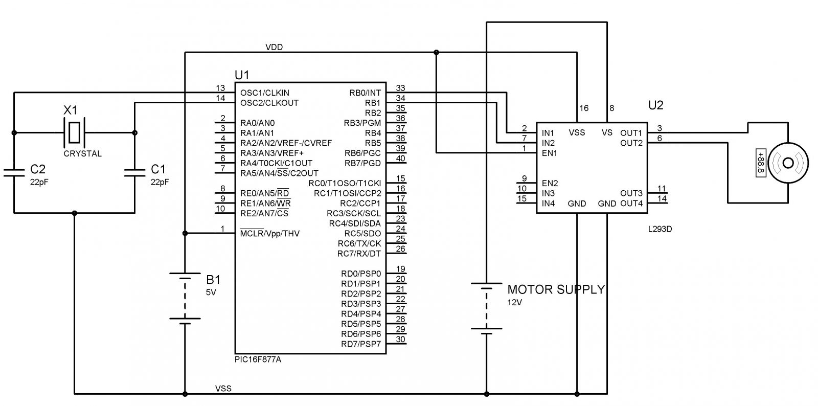 All inputs of these ICs are TTL compatible and output clamp diodes for inductive transient suppression are also provided internally. These diodes protect our circuit from the Back EMF of DC Motor.
In both ICs, drivers are enabled in pairs, with drivers 1 and 2 are enabled by a high input to 1,2EN and drivers 3 and 4 are enabled by a high input to 3,4EN. When drivers are enabled, their outputs will be active and in phase with their inputs. When drivers are disabled, their outputs will be off and will be in the high-impedance state.
For more detail: Interfacing DC Motor with PIC Microcontroller using L293D
- Why can't a microcontroller drive a DC motor directly?
Because DC motors require higher voltage and current than microcontroller I/O pins can provide and back EMF from the motor can affect the microcontroller. - What is an H-bridge and why is it used?
An H-bridge is a circuit using four switches to control motor direction and it solves current, voltage, and direction control issues for DC motors. - What are L293 and L293D?
They are dual H-bridge motor driver ICs that can control two DC motors in both directions and include internal clamp diodes for inductive suppression. - How much current can L293D provide?
L293D can provide bidirectional drive currents of up to 600 mA at voltages from 4.5 V to 36 V. - How much current can L293 provide?
L293 can provide up to 1 A at voltages from 4.5 V to 36 V. - Do these ICs protect against back EMF?
Yes, both ICs provide internal output clamp diodes for inductive transient suppression to protect against back EMF. - How are the drivers enabled on these ICs?
Drivers are enabled in pairs: drivers 1 and 2 by a high input to 1,2EN and drivers 3 and 4 by a high input to 3,4EN. - What happens when drivers are disabled?
When drivers are disabled, their outputs are off and in the high-impedance state.
