
Summary of Interfacing DC Motor with 8051 Microcontroller
Controlling DC motors with an AT89C51 requires a motor driver since microcontroller pins cannot supply required current or withstand back EMF. This article explains using L293D (quad H-bridge) to drive up to two DC motors, wiring IN1/IN2 to P3.0/P3.1 for direction control, EN1 to 5V, switches on P2.0/P2.1 for clockwise/anticlockwise rotation, and powering motors from a 12V battery/adaptor. L293D input logic combinations determine motor direction or idle state.
Parts used in the Interfacing DC Motor to 8051:
- AT89C51 microcontroller
- PCB board
- Programming cable
- 12V DC battery or adaptor
- L293D motor driver
- DC motor
- Electrolytic capacitor 10uF
- Ceramic capacitors 33pF (2)
- 10k resistors (1/4 watt) – 3
- Push buttons – 2
- Connecting wires
When we talk about controlling the robot, the first thing comes into the mind is controlling DC motors. Interfacing DC motor to the microcontroller is very important concept in Robotic applications. By interfacing DC motor to the microcontroller, we can do many things like controlling the direction of the motor, controlling the speed of the motor. This article describes you how to control the DC motor using AT89C51 controller.
Interfacing DC Motor to 8051 Circuit Principle:
The maximum output current of microcontroller pin is 15mA at 5V. But the power requirements of most of DC motors is out of reach of the microcontroller and even the back emf (electro motive force) which is produced by the motor may damage the microcontroller. Hence it is not good to interface DC motor directly to the controller. So use motor driver circuit in between of DC motor and controller.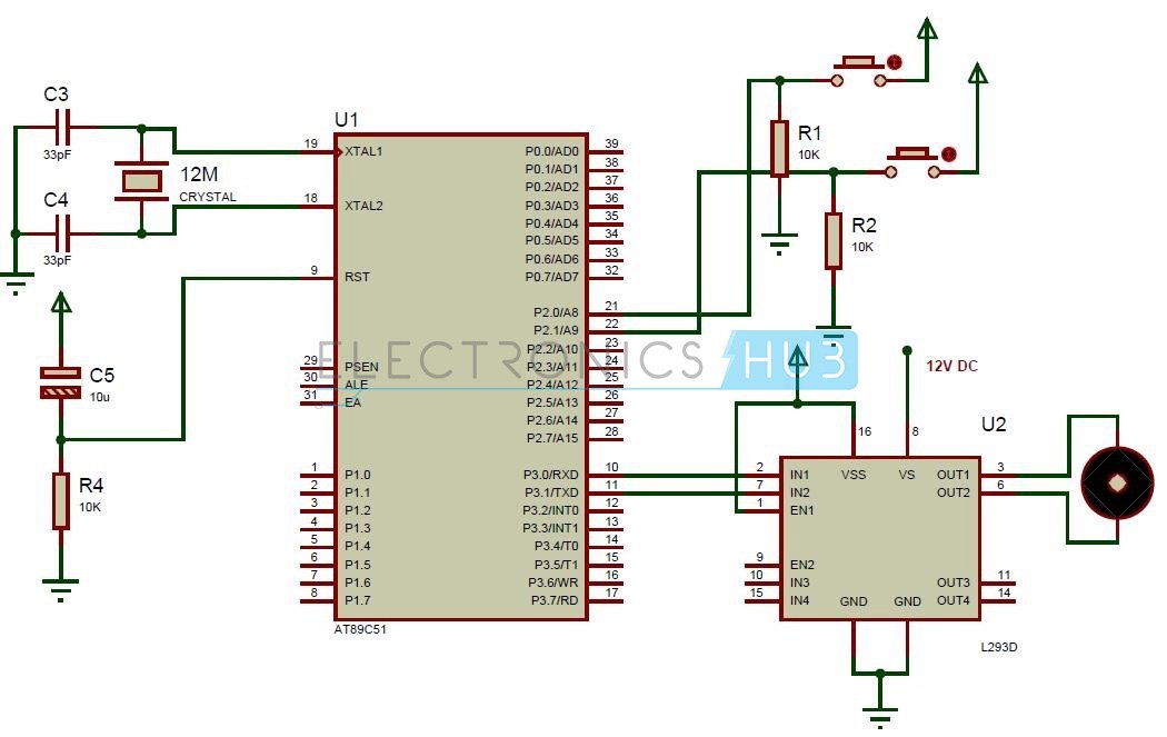
Also read the interesting concept: Interfacing 7 Segment Display to 8051 Microcontroller
Here, we are using L293D motor driver IC to drive DC motors. Using this IC, we can drive 2 DC motors at a time. For this IC motor supply is variable 4.5 to 36V and it provides maximum current of 600mA.
Circuit Diagram of Interfacing DC motor to 8051 Microcontroller:
Circuit Components:
- at89c51 microcontroller
- PCB board
- programming cable
- 12V DC battery or Adaptor
- L293D motor driver
- DC motor
- Electrolytic capacitor – 10uF
- 2 Ceramic capacitors – 33pF
- 10k resistors (1/4 watt) – 3
- push buttons – 2
- Connecting sires.
Get an idea about How PWM Based DC Motor Speed Controlling Circuit Works using Microcontroller
Interfacing DC Motor to 8051 Circuit Design:
The major components in the above circuit diagram are at89c51 microcontroller and motor driver. Here the motor driver input pins IN1, IN2 are connected to the P3.0 and P3.1 respectively to control the motor directions. DC motor is connected to output terminals of L293D. EN1 pin is connected to the 5V DC to drive the motor. Switches are connected to the P2.0 and P2.1 in pull down configuration. First switch rotates the motor in clockwise direction and second switch rotates the motor in anti clockwise direction. 8th pin of motor driver is connected to the battery directly.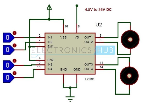
L293D Motor Driver:
L293D is a quadruple H- bridge motor driver, as the name suggests it used to drive the DC motors. This IC works based on the concept of H- Bridge. H-bridge is a circuit which allows the voltage in either direction to control the motor direction.
There are 4 input pins for L293D. Motors directions depends on the logic inputs applied at this pins. EN1 and EN2 must be high to drive the 2 DC motors.
- IN1=0 and IN2=0 -> Motor1 idle
- IN1=0 and IN2=1 -> Motor1 Anti-clock wise direction
- IN1=1 and IN2=0 -> Motor1 Clock wise direction
- IN1=1 and IN2=1 -> Motor1 idle
- IN3=0 and IN4=0 -> Motor2 idle
- IN3=0 and IN4=1 -> Motor2 Anti-clock wise direction
- IN3=1 and IN4=0 -> Motor2 Clock wise direction
- IN3=1 and IN4=1 -> Motor2 idle
For more detail: Interfacing DC Motor with 8051 Microcontroller
- Why can't the AT89C51 drive a DC motor directly?
Because the microcontroller pin maximum output current is 15mA and motor power needs are higher plus back emf can damage the microcontroller. - Which motor driver is used in the project?
The L293D motor driver IC is used. - How many DC motors can L293D drive at a time?
L293D can drive two DC motors at a time. - What supply voltage range does L293D support for motor supply?
L293D motor supply is variable from 4.5V to 36V. - Where are IN1 and IN2 of L293D connected in this design?
IN1 and IN2 are connected to P3.0 and P3.1 of the AT89C51 respectively. - What is the function of EN1 pin in the circuit?
EN1 is connected to 5V to enable driving the motor. - How are user switches connected and what do they do?
Switches are connected to P2.0 and P2.1 in pull down configuration; one switch rotates the motor clockwise and the other rotates it anti clockwise. - What logic on IN1 and IN2 makes Motor1 rotate clockwise?
IN1=1 and IN2=0 makes Motor1 rotate clockwise. - What logic on IN1 and IN2 makes Motor1 idle?
IN1=0 and IN2=0 or IN1=1 and IN2=1 make Motor1 idle. - How is the motor power connected in the circuit?
The motor power (pin 8 of L293D) is connected directly to the battery.
