IR Sensor Interface with PIC18F4550
In my previous project we have made a simple IR sensor Circuit. In this project, as promised before – we are going to demonstrate a PIC18F4550 microcontroller interface to IR sensor circuit. We are just going to glow few on the pic18f4550 as an example, however you can do some more intelligent operations by adding some more logics to the microcontroller coding. Interfacing infrared Proximity sensors with Microcontroller is quiet easy.
This project is not only about interfacing an infrared IR sensor module but also we are going to learn – How to take digital input from a PIC18F4550 Microcontroller (Reading the Input with a Microcontroller). It means that the source code here will work same for taking input from a simple switch. You can replace the IR sensor with some simple PUSH Switch or some other types of proximity sensors . In case of push button you would need to pull down the pin to ground with 1 k resistance, however for IR sensor you won’t need to pull down the input pin with resistor.
Infrared IR Sensor Module
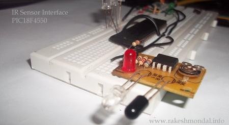
Let’s take a look at the IR Infrared Sensor Circuit Project module that we made in our previous project which is an inexpensive ( Low Cost ) sensor circuit module. You can find the schematic and PCB design in my previous post. There are three pins in the Schematic – Two pins for providing the input voltage and GND to the IR Sensor Module, and the third pin from the IR module is the IR control pin. This Control Pin from the IR sensor Module will be interfaced to the PIC18F4550 microcontroller for sensor input.
IR Sensor Module
Concept
The output from the IR sensor circuit will be connected to pins of a PIC18f4550 microcontroller and the microcontroller will regard it as digital input to read either 1 or 0. According to the output from the IR sensor module, the PIC18F4550 will respond by glowing led. Since we just want to read some voltage in the microcontroller as input (either High or low) hence we are going to configure input pins as digital to read just 1 or 0 from the sensor.
PIC18F4550 Interface with IR sensor Circuit
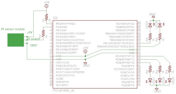
The output from the IR sensor circuit is connected to RA0 of the pic18f4550 which is configured as input with TRISB registers, and the output will be displayed on LED connected across RD7, RD6,RD5 (PORTD) and RB0 and RB1 (PORTB) which are configured as output pins. Follow the schematic below.
Schematic (IR sensor and PIC18F4550 microcontroller)
In this project we don’t need to perform any Analog to Digital Conversion(ADC), hence we are going to turn the ADC off (ADCON0bits.ADON = 0) and configure all the PINS to Digital. At the default 1 MHZ oscillator frequency the output sometimes gives unstable result, hence tuning the microcontroller to 8MHZ solved the problem, Please note that pic18f4550 works by default on 1 MHZ and you can change the OSCCON bits settings to tune the oscillator frequency according to your requirement.
Search in pic18f4550 datasheet for OSCCON register bits and you will find a nice description and bits settings table for available oscillator frequency and settings to configure the microcontroller oscillator frequency. Here I have configured the internal oscillator to 8MHZ to avoid switch debouncing. However it works well with 1MHZ settings as well. As a better plan the comparator is also turned off to avoid any conflict.
All the resistors in the above Schematic is 1k resistance. If possible, it is also recommended to add a IC 7805 liner Voltage regulator IC as a source of +5V to avoid any voltage fluctuation which could possibly damage the microcontroller. Make sure the input voltage to pic18f4550 must never exceed +5v. Please do read the excellent pic18f4550 datasheet provided by microchip.
For more detail: Infrared IR Sensor Interface with PIC18F4550 Microcontroller
