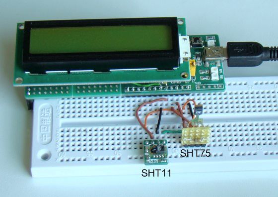
In Part 1 of this tutorial, we discussed about Sensirion’s SHT1x and SHT7x series of humidity sensors, their interface specifications, the communication protocol used for transferring data in and out of the sensor, and the equations to convert their digital outputs to actual physical quantities. These sensors are capable of measuring temperature along with relative humidity and provide outputs in fully-calibrated digital words. We will now see how a PIC microcontroller can be programmed to communicate with these sensors, read the temperature and relative humidity data, and display the information on a character LCD.
Circuit Diagram
We will be interfacing the SHT11 and SHT75 sensors simultaneously to different port pins of PIC18F2550 and display the measured values of relative humidity and temperature from both on a 16×2 character LCD. The two sensors are placed next to each other and are supposed to measure the same values for relative humidity and temperature. The circuit diagram below shows the connection of the two sensors and a 16×2 character LCD to StartUSB for PIC board. StartUSB for PIC is a small development board for PIC18F2550 from mikroElektronika. The microcontroller comes preprogrammed with a bootloader, and therefore, no external programmer is required.
The LCD is operating in 4-bit mode, where the data pins D4-D7 are driven by RB4-RB7 pins of PIC18F2550. The RS and E pins are connected to RC6 and RC7 respectively. The clock lines of SHT11 and SHT75 are driven separately by RB1 and RB3 pins of PIC18F2550, respectively. On the other hand, the RB0 and RB2 pins are connected to the data pins (SDA or DATA) of SHT11 and SHT75, respectively. A decoupling capacitor (100 nF) is connected between Vcc and Gnd pins of each sensor. The PIC18F2550 microcontroller on-board StartUSB for PIC board runs at 48 MHz using the internal PLL along with an external 8.0 MHz crystal. A pull-up resistor of 10 K is required for each DATA line (in fact, the SHT11 board from mikroElektronika has pull-up resistors of 1 K on both DATA and SCK lines, but the manufacturer’s datasheet recommends 10 K).
Software
The sensor’s serial communication protocol was described in Part 1. We will implement it for PIC18F2550 using mikroC Pro for PIC. MikroElektronika provides a sample code written in mikroC for reading temperature and relative humidity from a SHT11 sensor. This code was later modified by Uroš Pešović (from Serbia) in order to account for the new conversion coefficients released by Sensirion for its version 4 sensors. I am adapting the same code for dual sensor case with some modifications that are required for our specific case.
The following subroutine is to reset the interface, in case the communication to the sensor is lost. In our case this routine will be always called before sending a new measurement command to the sensor. In order to pull the DATA line high, all you need is to define the direction of PIC port pin driving the DATA line as input. The pull-up resistor will then pull the line high. However, the same port pin direction must be defined as output and set to logic ’0′ to pull the line low.
void SHT_Reset() {
 SCL = 0;                     // SCL low
 SDA_Direction = 1;           // Define SDA as input to pull the DATA line high
 for (i = 1; i <= 10; i++)    // repeat 18 times
 SCL = ~SCL;                  // invert SCL
 }
Once the connection is reset, you need to send a Start Transmission sequence. The subroutine for this would be something like this.
For more detail: Humidity and temperature measurements with Sensirion’s SHT1x/SHT7x sensors using PIC18F2550 (Part 2)

