Summary of How to Make a Universal Usb Pic Programmer PICkit 2
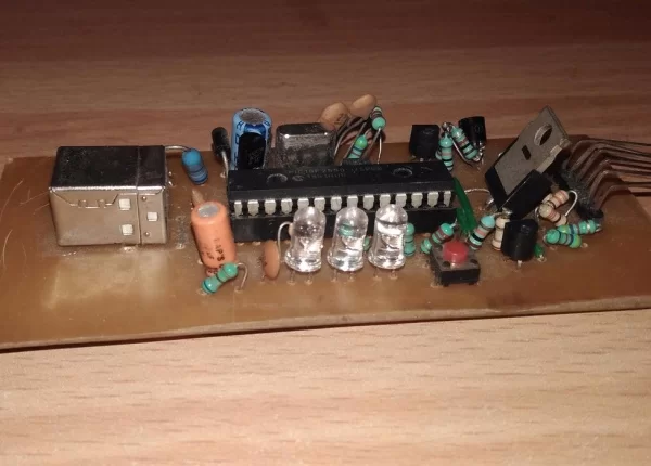
The PICKit2 is a USB-powered universal programmer using the PIC18F2550 microcontroller. It converts 5V USB power to 12V for programming via a Buck converter and manages voltage outputs (Vdd/Vpp) through MOSFET switching. The circuit includes crystal oscillators, feedback networks, status LEDs, and current-limiting resistors for programming lines. Substitutes are provided for unavailable components like diodes, MOSFETs, and inductors to facilitate cloning.
Parts used in the PICKit2 Programmer:
- PIC18F2550 Microcontroller
- Crystal Oscillator X1
- Capacitors C1, C2, C3, C4, and 330nF or .1mF
- Inductor L1 (470uH – 1mH)
- MOSFETs Q1, Q2, Q3, Q4, Q5, Q6
- Diodes D1 and D2 (BAT85, 1N5819, or 1N5818)
- Resistors R1 through R17
- LEDs LED1, LED2, and LED3
Subscribe us on YouTube for updates http://www.youtube.com/channel/UCsSdGsFs8Cby3oxiMHTCNEg?sub_confirmation=1
PICKit2 is a USB powered device, that is it gets power from PC USB +5V power supply. USB microcontroller PIC18F2550 is the soul of the PICKit2. The USB Data+ and Data- from PC are connected to the D+ and D- pins of the PIC182550. The built-in-clock generator of pic uses external crystal oscillator X1, C2 and C3 to ensure the correct system clock rate. The inductor L1, MOSFET Q1, diode D1, capacitors C1 and C4 forms a DC-DC converter (Buck Converter) which converts 5V from PC to 12V, which to be applied to MCLR/VPP pin of a microcontroller at the time of programming. This is controlled by the PIC firmware. The resistors R2 and R3 forms a voltage sensing feedback network, which is given to the analog pin AN0 of the PIC. MOSFET’s Q4, Q5 and resistor R5 are used for switching Vpp to MCLR/Vpp output. The MOSFET Q6 and resistor R4 ground the MCLR output whenever required. The MOSFET Q3 and resistor R16 are for switching Vdd to output whenever required. The Vdd sensing feedback is given to the analog pin AN1 of the PIC via resistor R6. The MOSFET Q2 with resistors R1, R17 provides active pull down to Vdd output whenever required. The diode D2 protects the circuit from external Vdd.
The LED1 with current limiting resistor R12 indicates that the circuit is powered form USB. The LED2 along with current limiting resistor R11 indicates that Vdd is switched to output. The LED3 with current limiting resistor R10 is controlled by the PIC firmware, normally glows during read and write operations indicating busy states.
The resistors R7, R8 and R9 are current limiting resistors in series with output lines PGD, PGC and AUX. The resistors R14 and R15 ensures active low at PGD and PGC outputs in certain cases.
Subscribe our Youtube channel – http://www.youtube.com/channel/UCsSdGsFs8Cby3oxiMHTCNEg?sub_confirmation=1
Components that I used in my clone are shown as bold.
The protection diode D2, BAT85 will drop much more voltage on Vdd. So if you wish to avoid the voltage drop you can short it. If you don’t want to completely eliminate the protection you can replace BAT85 with lower drop Schottky diode. Thus you can replace it with 1N5819 or 1N5818.You can replace the MOSFET Q3 (IRF9Z34) with cheaper BC640, in this case the output current will be limited to few hundred milliamperes with an acceptable voltage drop. You can also replace IRF9Z34 with IRF9540N if it is not available in your city.Inductor L1 can vary between 470uH – 1mH and should atleast 150mA rated. BS170 can be substituted by VN2010L or BS107BS250 can be substituted by VP2020L or BSS92 (be careful, BSS92 has different pinout!) or BC 557 with base resistor 1KYou can omit the 330nF capacitor. I used .1mF capacitor.Components that I used in my clone is shown as bold.
Step 2: Download
You can download the Softwares and Latest version of hex file from Microchip’s Website. You can download the Hex file, Schematics, PCB Design, Component Layout etc from here…
Subscribe our Youtube channel – http://www.youtube.com/channel/UCsSdGsFs8Cby3oxiMHTCNEg?sub_confirmation=1
Follow us – https://www.facebook.com/ddelectrotech/
Source: How to Make a Universal Usb Pic Programmer PICkit 2
- How does the PICKit2 receive power?
It is a USB powered device that gets power from the PC USB +5V power supply. - What converts 5V to 12V for the MCLR pin?
An inductor L1, MOSFET Q1, diode D1, capacitors C1 and C4 form a DC-DC Buck Converter controlled by firmware. - Can I substitute the BAT85 diode?
Yes, you can replace it with 1N5819 or 1N5818 to avoid voltage drop, or short it completely. - What are the substitutes for MOSFET Q3?
You can use BC640 for lower cost or IRF9540N if IRF9Z34 is unavailable. - Can I omit the 330nF capacitor?
Yes, you can omit the 330nF capacitor and use a .1mF capacitor instead. - Where do I download the software and hex file?
You can download them from Microchip's Website or the provided link for schematics and PCB design. - Which pins connect to the PC Data+ and Data-
The USB Data+ and Data- from the PC connect to the D+ and D- pins of the PIC182550. - What indicates the busy state during operations?
LED3 glows normally during read and write operations to indicate busy states.