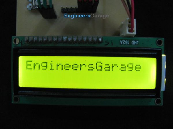
How to interface 16×2 LCD in 4-bit mode with PIC18F4550

The 16×2 character LCD can work in two modes, namely, 8-bit and 4-bit. These modes basically correspond to the number of data pins used in interfacing LCD. 8-bit mode uses all the data lines and has been explained in LCD interfacing with PIC18F4550. In 4-bit mode, only four data pins of LCD are connected to the controller. This mode, thus, saves four pins of the controller unlike 8-bit mode. The configuration and display method of LCD in 4-bit mode has been explained here.

interface 16x2 LCD

The 8-bit mode of LCD interfacing with PIC has been explained earlier. In the 4-bit mode the (8-bit) data/command is sent in nibble (four bits) format to LCD. The higher nibble is sent first followed by the lower nibble. In 4-bit mode only four data pins (D4-D7) of LCD are connected to the controller. The control pins (RS, RW and EN) are connected the same way as in 8-bit mode. The connections of LCD with PIC18F4550 are shown in the adjoining circuit diagram. Please note that here only PortB is used to connect data lines as well as control lines unlike in 8-bit mode. Refer LCD interfacing with PIC in 8-bit mode.

LCD is configured for 4-bit mode by sending appropriate instruction known as Function Set. The Function Set is hexadecimal instruction for LCD MPU unit which selects the working modes of LCD. The Function Set is given below along with its description.
Instruction
RS
RW
D7
D6
D5
D4
D3
D2
D1
D0
Function Set
0
0
0
0
1
DL
N
F
Description: 
DL       –           Data Length
N         –           No. of Lines
F          –           Font
 Value
 DL
 N
F
1
8 bit
2 lines
5×10 dots
0
4 bit
1 line
5×7 dots
According to the table, the value of Function Set for 4–bit mode will be [ 0010 0000 ] 0x20. The value of Function Set for the LCD configuration : 2 line (N=1), 5×7 dots (F=0) and 4-bit (DL=0) mode will be [ 0010 1000 ] 0x28.
It is important to note that when the power supply is given to LCD, it remains in 8-bit mode. In this state if 0x20 is sent, lower nibble will not be received by LCD because only four data lines (D4-D7) are connected, so 0x02 is sent instead of 0x20.

About The Author

Ibrar Ayyub

I am an experienced technical writer holding a Master's degree in computer science from BZU Multan, Pakistan University. With a background spanning various industries, particularly in home automation and engineering, I have honed my skills in crafting clear and concise content. Proficient in leveraging infographics and diagrams, I strive to simplify complex concepts for readers. My strength lies in thorough research and presenting information in a structured and logical format.

Follow Us:
LinkedinTwitter