The purpose of this project was to create an electronics kit for teaching entry level programming of embedded systems. The kit includes a development board, external hardware modules, software, and teaching materials. The hardware modules consist of a LCD display, Keypad and various user I/O. These modules were then incorporated into lessons for creating several working projects including a Calculator, Clock, Morse Code Interpreter, a Maze Game and Simon Says.
1 Introduction
Embedded systems are integral part of modern life. They help get where we need to go by running many of the systems in cars and planes.They operate our watches, our phones, and our tablets. They control the robots that can manufacture a car, clean a house, or perform surgery. They even improve our everyday activities with ereaders for books, DVRs for TV, watches that record our exercise, and so many other devices. New uses for embedded systems are created every day, as manufacturers take complex tasks, and reduce them to the push of a button.
The purpose of this project was to create a kit meant to teach entry level embedded systems to buyers. There are three parts to the kit hardware, software, and teaching materials. The hardware component consists of a development board and a series of modules contain the various components needed during the course. The software component consists of the libraries needed to drive the development board and the modules. The teaching tools consist of the documentation of all parts of the project and a series of detailed lessons with designed to teach the basics of embedded systems. These lessons will have two phases the teaching phase where the students will learn new concepts, through a series of hands on assignments and the implementation phase where the students will use the learned concepts to complete an project. The projects are fully functioning applications either serving some basic utility, or a working
game so that students will enjoy using their own work and take pride in developing on their own..
2 Background
2.1 CPU and Microprocessors
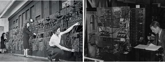
The core of computer circuitry is the central processing unit, or CPU, which carries out the logical, arithmetic, and control operations necessary to carry out the instructions of a computer program (Zandbergen). The CPU was first introduced with the implementation of “storedprogram computers”, computers that stored program instructions within electronic memory. The first electronic general purpose computer was the ENIAC (Electronic Numerical Integrator and Computer), built in February, 1946 (Copeland). The ENIAC and other computers like it had to be physically rewired to perform individual tasks, earning the moniker “fixedprogram computers.” Later computer models, such as the EDVAC (Electronic Discrete Variable Automatic Computer) were designed to perform instructions of various types without needing to modify the computer circuitry. Programs written for the computer were stored in
computer memory, and modifying the memory would change what operation was performed. These early CPUs used relay switches and vacuum tubes as switching devices, and computers often needed thousand of these switching devices to run. As a result, early CPUs were fairly bulky in size.
With advancements in technology, CPUs could be made smaller, and could house more complex circuitry, allowing for multipurpose capabilities. Starting in the 1960s, transistors, semiconductor devices that could amplify or switch electronic signals, were used to replace the bulkier and fragile vacuum tubes. Circuits of interconnected transistors could be manufactured in a compact space, and then printed on a single semiconductorbased chip (tomshardware.com). These “integrated circuits” started as basic, nonspecialized circuits, and CPUs would need a numerous quantity of integrated circuits to run. Additional transistors could be added to the integrated circuits, improving their capabilities even further.
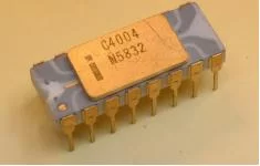
Intel introduced their first microprocessors, the 4bit Intel 4004 and 8bit Intel 8008, in 1971 and 1972 respectively (meetingtomorrow.com).. In comparison to other CPUs which required multiple integrated circuits, microprocessors could run on a single integrated circuit, which greatly reduced the cost of processing power (Singer). Microprocessors were faster, more efficient, lighter, and a fraction of the size of previous CPUs. Their manageable size and efficiency has rendered all previous CPU models obsolete. Modern processors are even more efficient, operating on the nano level rather than the micro level, although, they are still referred to as microprocessors.
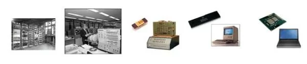
Microcomputer powered by Intel 8008, 1984 Apple Macintosh, 2013 Dell Insperion)
2.2 Microcontrollers
Microcontrollers are a selfcontained system containing a processor, memory and peripherals. They are meant to be a cheaper, more cost effective solution for systems that need the abilities of a processor, but are not hardware intensive (robotplatform.com). For reference, a modern commercial processor could cost between $300 and $1000, while a microcontroller can be as little as a few cents.
The history of microcontrollers is tied to the history of the microprocessor. While the Intel 4004 was revolutionary in redesigning CPUs, the microprocessor required external memory, a motherboard and many other components, making any system that used them very expensive. The price of manufacturing made it costineffective to use microprocessors when building appliances and other devices that weren’t meant for major computation.
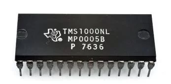
In 1974, Texas Instruments (TI) released the TMS 1000, which had readonly memory, read/write memory, processor and clock on one chip (circuitstoday.com). The cost required to produce this was greatly reduced in comparison to other microprocessors. Other companies, including Intel, followed suit by crafting their own microcontrollers, which were optimized for singular applications.
The modern microcontrollers are a very diverse in both their specifications and their uses. They range from very fast, capable of running complex systems and devices such as smartphones, to one’s meant to run lights. The diversity is a great as their applications in modern life: high power, low power, 8 bit, 64 bit, slow, fast, large memory, small. They now run most appliances, devices, toys, gadgets, and almost any other electrical system (circuitstoday.com).
2.3 Existing Kits
The idea of an educational tool designed to teach embedded computing is not a
completely new idea. There are a number of kits that have been produced in the past that have
been built for this exact purpose. The number of kits produced for this purpose is admittedly
small, especially when viewed in comparison to educational kits devoted to other disciplines.
Also, many of these kits are out of date, or have been discontinued, meaning that the market of
embedded computing kits is virtually untouched.
There are a few theorized reasons why this market is so small. Embedded computing is a subject that is very indepth and complex, more than electrical circuits or basic programming.
Starter kits are very expensive, and the software needs to be kept uptodate to stay relevant. Most kits are not actually educational in nature, and assume the user is experienced with microcontrollers and has purchased the kit with the express purpose of building their own application, rather than learning how to program.
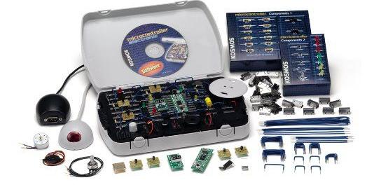
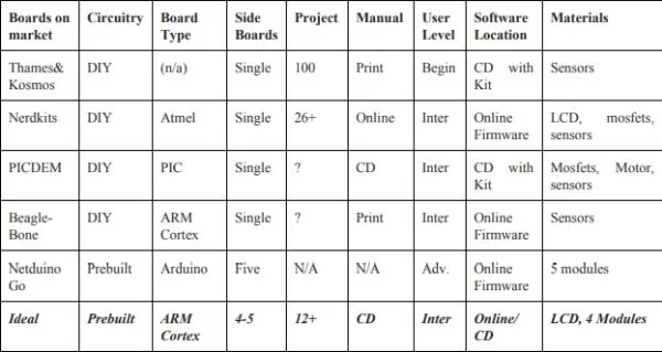
The first item for review is the Thames & Kosmos Microcontroller Computer Systems Engineering Kit. The kit includes a portable carrying case that has a main board and additional circuit components, a cable to connect the board to a computer, a CD containing the programming software, and an instruction booklet with directions for projects. The user needs to set up and wire the board by hand for each individual project, and the instructions for how to do so are contained within the manual.The product was discontinued in 2006 or 2007, and the software is not compatible with modern operating systems (www.parentschoice.org).
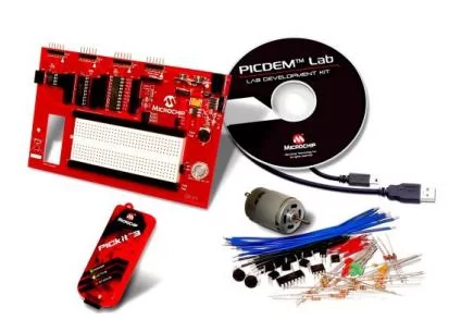
The PICDEM Lab Development Kit shares similarities with the Thames & Kosmos kit. The kit consists of a customizable board, an array of sensors and other circuit components, a CD containing software, a cable to connect to the board, and a virtual instruction manual with handson projects.The PICDEM kit has multiple PIC microcontrollers rather than a single microcontroller board. The kit is still available for purchase (www.microchip.com).
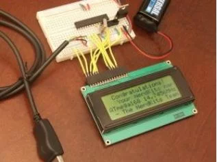
The Nerdkits Microcontroller Kit was developed by a team of MIT graduates to teach Electrical engineering and Software Development. The boards are composed of basic components that can be replaced easily. The kit includes an instruction guide that gives stepbystep instructions on how to perform the electrical wiring and how to write and compile programs. Sample projects are located on the website with videos on how to perform them. The kits are no longer being distributed (www.nerdkits.com).
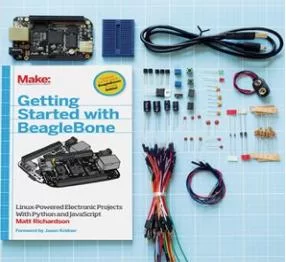
The last kit researched was the Getting Started with the BeagleBone Black Kit, which features a the BeagleBone, a Linuxbased microcontroller board with the programming capabilities of an Arduinolevel microprocessor. The kit contains the BeagleBone board, an instruction manual with project applications, and an array of capacitors, resistors, LEDs and other circuit components(www.makershed.com).
There were noticeable similarities between the different kits. Each kit was packaged as a disassembled unit, with a microcontroller, a solderless breadboard, and additional wires, resistors, LEDs, buttons, and sensors. The user had to connect the microcontroller to the breadboard, and wire the breadboard with the necessary electrical components needed to construct whatever application was presented.
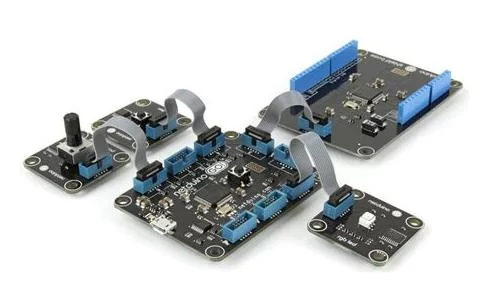
Any of the other embedded kits that were found while researching were specialized kits used to design custom applications. These kits were meant to be used by experienced programmers, lacking instructional materials of any sort. Despite this, there was one kit that had a unique feature that caught our notice. The Netduino Go Starter Kit consisted of a main board with Netduino microprocessor, and 4 additional module boards that worked in conjunction with the main board. Each module had a few built in components, and could be easily connected to the board. This made the board more easy to use for a wide variety of applications (www.adafruit.com).
3 Methodology
The methodology section will cover what we did during the course of the project. It will start with the initial meeting and planning of our project. It will then cover the selection and programming of our development board. Then it will discuss the design process of the extensions which became modules and the lessons we planned to teach. We will also discuss the construction and implementation of those modules and the choices we made. We will conclude with our creation and testing of the lessons.
3.1 Initial Planning
This project began when we separately came to Professor Bitar and proposed a kit dedicated to teaching students the basics of ECE. Alex proposed a kit that would teach student how to assemble basic hardware circuits, while Steven proposed a kit that would teach students the basics of embedded systems. Professor Bitar asked us meet together with him to see if we could combine our efforts and work together. After spending some time working together and brainstorming ideas, we decided to unify our project ideas. The final proposal was to create a kit that taught the basics of embedded programming and leave open the possibility of teaching students how to make and program components for an embedded circuit.
Now that we had decided what type of kit, we had to determine the scope of the project, we could not make a kit that would be useful to everyone. First we had to decide who our target demographic was. We debated what age group, and knowledge level the kit should be tailored to. The options for age group were divided by educational divisions: Middle School, High School, and College. We wanted the kit to teach the students skills that could be used outside the scope of the kit itself, and we wanted them to know and understand what they were doing, not just doing as they were told. As such we decided to aim the kit at High Schoolers, and early college students, as this group would understand the knowledge presented, while not be advanced enough that it would be too simple. The second part of this stage was to determine the level of knowledge that the students should have coming into the project. Should we make a kit for someone who has no knowledge of programming, or an advanced knowledge? We decided to develop a kit for someone who has basic knowledge of programming C, but little to no experience with embedded systems. We did this because we wanted a kit to teach embedded programming, the creation of an application using both hardware and software. We did not want to have teach the students how to program from scratch. We use common programming terminology, which we did not want to teach. To summarize, we decided to build a kit for High School/College level students, who know how to program but wish to learn embedded systems, the basics of those systems.
Now that we knew who would be using the kit, and their background, we had to decide where the kit would be used. Was this a classroom tool, to be used by teachers to teach their student, or was it a DIY (Do it Yourself) Kit? We decided that this would be a DIY Kit, that would teach its user the topics. It could still be used by a teacher as a classroom tool, but we wanted it to be a commercial product for individual use, first and foremost.
The final step of of this stage was to determine what our kit should contain, and what we needed to deliver for our project. We split the kit into three types of deliverables: hardware, software, and lessons. For the hardware we would need a development board, that would serve as the center of our kit and an expansion(s) board that would add any hardware we wanted but was not included on the development board. For the software we would need to deliver a software library for the kit, complete with examples that would allow the student to use the hardware from the start. The lessons are the documents that would teach the students how to use the kit, and give them projects to do as they learn.
3.2 Designing the Lessons
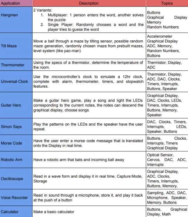
We had the basic idea for the kit: who would use it, where, and what was should be in it. Now we had to determine how it would teach. As the the kit was meant to be DIY, we wanted to keep it interesting, as such we decided that we wanted to teach by application. We wanted to create a series of applications that would cover cover the material we wanted to teach, well giving to students a sense of accomplishment (and a new toy to play with). We then brainstormed a series of applications that could be done by in an introductory course, and either had utility (a clock) or was a game (Simon Says). The results of this can be seen in Figure 3.1.
At this point we realised that we would have to teach the students the individual components one at a time, but we wanted to keep them learning by doing not by reading blocks of text. So we decided that to change the format from one large application, to a Lesson. A Lesson would be a series of Assignments, with some text explanations, that would culminate in a Project to build the application. This would allow the students a very hands on learning experience, while giving them the sense of building towards a goal: the application.
3.3 Development Board
We had a plan, we knew our target demographic, we knew what we wanted to teach, and how, now we had to begin building the kit. The first step was to choose a development board to use, as it is the central component of the kit and it is needed to develop any other components. We began by making a list of criteria for the board. The first criteria was that the board had to be very expandible, this would allow us to add any hardware our projects needed. The second criteria was usability, we did not want an over complicated microcontroller as that would make the kit harder to use. We also wanted the board to have minimal built in hardware, allowing it to change its functions based on the hardware it was connected to. The third criteria was versatility, we wanted the lessons that the students learned using the kit, and the board itself, to be usable in future projects. We wanted to get our students started on the path, and we wanted them to continue down it after.
The first step in choosing a board was to choose an architecture to use. We examined three architectures that we had used previously and had at least some experience with: ARM, Arduino, and MSP430. To decide which architecture was best suited to the purpose of our project we examined the prevalence of the architecture, its uses, the availability of software, and other criteria, see Figure 3.2 for more details.
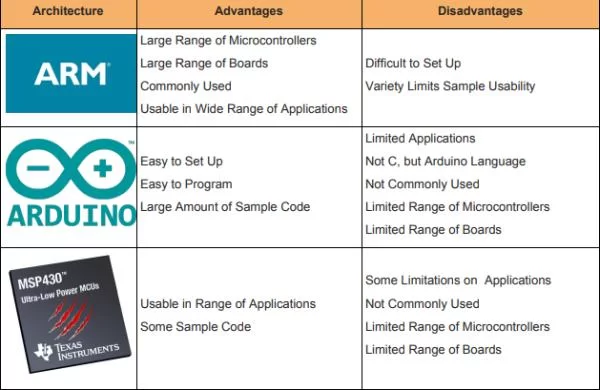
MSP430 was the first architecture we ruled out, it had limitations in some applications, a small number of available boards, and few advantages to speak for. This left it a competition between Arduino and ARM. Arduino was easy to set and use, but had very little real world applications. Additionally Arduino had a large following among hobbyist leading to large samples and libraries, but did not use conventional C, limiting the use of the skills learned. ARM is a very prevalent architecture, with a wide range of boards, but the libraries tend to be restricted by microcontroller. ARM is generally more complex, harder program and set up. In the end we decided that we could overcome the disadvantages of ARM with some hard work on our end, by creating libraries to reduce the program difficulty and having presetup projects.
Now that we had an architecture, we had to choose a the board itself. On the recommendation of several professors, we decided to select a board from Olimex, a manufacturer that specializes in making development boards for education purposes. Olimex provided several useful advantages, the first of which was that they sell various hardware modules that connect to their proprietary UEXT port. Secondly they provide sample code for most of their boards. These two features could save us a large amount of time and effort. We began to examine Olimex’s expansive selection of ARM development boards. There were several boards that fit our criteria , but one stood out: the STM32H152, see Figure 3,3.
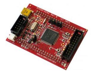
It has two 2×20 extension ports, a UEXT port, and was only $18. It also had extensive libraries provided, as well as example projects in both eclipse and IAR Embedded Workbench ARM (EWARM). For the full detail, visit: https://www.olimex.com/Products/ARM/ST/STM32H152/
This seemed to fit all our criteria, it was simple, expandable, and code libraries that would give a place to start. The STM32H152 uses the STMicroelectronics STM32L152VBT6 microcontroller which is part of the STM32 series of ARM microcontrollers. For the full details For the full product specifications of the STM32L152VBT6 visit: http://www.st.com/content/st_com/en/products/microcontrollers/stm3232bitarmcortexmcus/s tm32l1series/stm32l151152/stm32l152vb.html?sc=internet/mcu/product/248824.jsp
Unfortunately, this was when we ran into our first, and largest, difficulty. Once the board arrived, we found the libraries provided by Olimex to be either incomplete or flawed. We were forced to find and alternative library, we turned to the manufacturers of the microcontroller,
STMicroelectronics, who had set of libraries for their STM32L1xx line, called the STM32CubeL1. This cube only contained projects and code configured for the development boards built by STMicroelectronics, and their corresponding microcontrollers. Fortunately one of the development board uses a very close microcontroller, the STM32L152C. This allowed us to get our microcontroller booted. Unfortunately the documentation for the libraries was broken, we were forced to puzzle out their construction through trial and error. As we adapted them to match our microcontroller and board. As we explored their construction we made the necessary adaptations to make the libraries functional for our board. After large amount of time, we gained a sufficient understanding the libraries, called the HAL drivers to find and properly adjust them.
3.4 The Modules
In parallel to the choosing and programing of the development board we began to plan how we would expand whichever board we would choose. There were two methods that we discussed, the first was a traditional daughterboard that would contain as much hardware as we could fit. The second was a series of interchangeable modules, based partly on the modules provided by Olimex, and partly on the shields used by Arduino. The daughterboard would be allow us to create a single multipurpose board, it would be complex and would have limited use outside of the kit. The module design would create many single purpose boards, each would have a simple design, but the amount of boards would complicate the projects. We decided to use the Modules because it would allow the kit to be expanded by creating more modules, additionally it would make the kit more versatile, and ,we believe, more interesting to use.
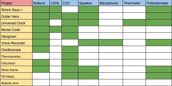
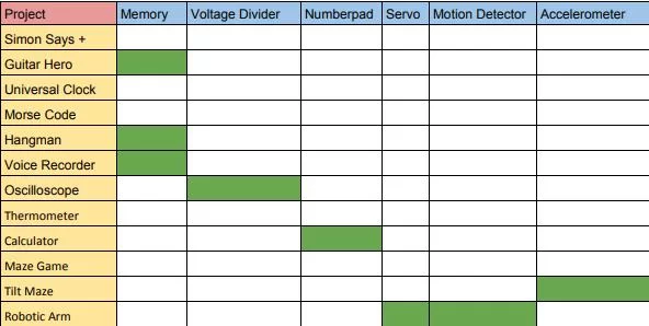
Once we had our our development board chosen, we needed to map out the hardware needed by each project, so that we could determine what was needed on our modules. The full details of this can be seen in Figures 3.4 and 3.5.
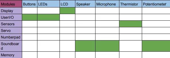
We also had to plan how the modules would connect to the development board. Both of the 2×20 ports on the STM32H152 have their own power lines, and connections to 34 Pins on the microcontroller, additionally we had the UEXT port and the Olimex modules. We designed six single purpose modules, to contain the hardware that we would need, see Figures 3.6 and 3.7.
As we now knew what hardware each project required and what hardware each module contained, we combined the information to see which modules each project would require, see Figure 3.8 for the full details.
Source: Embedded Instruction Kit