Summary of Display custom characters on 16×2 lcd using Microchip Pic16f877 Microcontroller
This project demonstrates generating and displaying custom characters on a 16×2 LCD using a Microchip PIC16F877 microcontroller. By defining character patterns in arrays, the code writes these to the LCD's CG-RAM, allowing symbols like hearts or rockets to appear alongside standard ASCII text. The process involves initializing the LCD, setting up the microcontroller ports, and cycling through custom character codes to render them on the display screen.
Parts used in the Custom Characters on 16x2 LCD Project:
- Microcontroller PIC16f877
- 16×2 LCD
- Potentiometer (For Setting lcd Contrast)
- Crystal 20MHz
- Connecting wires
- Power Supply
- Bread board or PCB for circuit
- MP-LAB ide
- High TECH C compiler
- Proteus 8.0 simulation software
Here is a simple project on how to build/generate/make custom characters in 16×2 lcd and then print/display them on lcd using microchip pic16f877 microcontroller. Character lcd contains a set of ascii characters and some Chinese characters in their controllers. We invoke the ascii characters present in the ram for displaying them on lcd. But if we want to display some special characters, symbols or similes we first have to make/declare them in the ram of lcd controller since they are not present in the ascii character set of the lcd. Then we can invoke them for displaying on the lcd when ever is required.
Building and displaying self made custom characters on lcd is not a very hard task. To carry out this task you must know about the internal structure of character lcd. The size of the lcd controller ram, registers of the lcd and CG-RAM(Character generated ram) of lcd. CG-RAM is the most important part of lcd for generating and displaying self made custom characters. CG-RAM is a whole big topic so it is kept in a separate post. CG-RAM is fully discussed in the tutorials below. I recommend you to please take the tutorials other wise you will not unable to understand the code below.
- How to generate Custom Characters in CG-RAM and display them on lcd.
- 16×2 lcd working, pinout & registers.
Project Requirements.
- Microcontroller PIC16f877
- 16×2 lcd
- Potentiometer (For Setting lcd Contrast)
- Crystal 20MHz
- Connecting wires, Power Supply, Bread board or PCB for circuit.
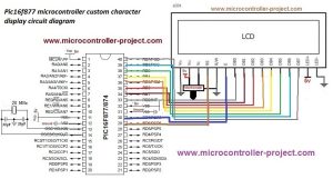
Circuit diagram of the project is given below. Port-B of Pic16f877 microcontroller is connected with data pins of lcd. LCD controlling pins en(enable), rs(register select), r/w(read/write) are connected to Port-D pin 6 and 7. R/W(Read/Write) pin is grounded because we are only writing to lcd, Grounding the R/W pin enables the write operation for lcd. All the other connections are necessary connections to brought the microcontroller and whole circuit in working condition.
To understand the code you must first know the internal structure of lcd. The tutorials links given above are very helpful for understanding the working and internal structure of CG-RAM of lcd. If you didn’t take the tutorials. I recommend you to please go through them before going through the code below.
| #include <htc.h> | |
| #define __XTAL_FREQ 20e6 | |
| #define en RD7 | |
| #define rs RD6 | |
| #define rw RD5 | |
| char c1[8]={0x04,0x0E,0x0E,0x0E,0x1F,0x04,0x00}; | |
| char c2[8]={0x00,0x0A,0x04,0x04,0x00,0x0E,0x11}; | |
| char c3[8]={0x04,0x0A,0x11,0x11,0x0A,0x04}; | |
| char c4[8]={0x0E,0x0A,0x1F,0x1B,0x1F,0x0A,0x0E}; | |
| char c5[8]={0x0A,0x04,0x04,0xA,0x11,0x04,0x11}; | |
| char c6[8]={0x04,0x0A,0x1F,0x0A,0x15,0x1B,0x11}; | |
| char c7[8]={0x1F,0x11,0x11,0x11,0x11,0x11,0x1F}; | |
| char c8[8]={0x1F,0x1D,0x1B,0x1D,0x1F,0x10,0x10}; | |
| void delay(unsigned int time) //Time delay function | |
| { | |
| unsigned int i,j; | |
| for(i=0;i < time;i++) | |
| for(j=0;j < 10;j++); | |
| } | |
| //Function for sending values to the command register of LCD | |
| void lcdcmd(unsigned char value) | |
| { | |
| PORTB=value; | |
| rs= 0; //register select-rs | |
| rw = 0; //read-write-rd | |
| en = 1; //enable-e | |
| delay(50); | |
| en=0; //enable-e | |
| delay(50); | |
| } | |
| //Function for sending values to the data register of LCD | |
| void display(unsigned char value) | |
| { | |
| PORTB=value; | |
| rs= 1; //register select-rs | |
| rw= 0; //read-write-rd | |
| en= 1; //enable-e | |
| delay(500); | |
| en=0; //enable-e | |
| delay(50); | |
| } | |
| //function to initialize the registers and pins of LCD | |
| //always use with every lcd of hitachi | |
| void lcdint(void) | |
| { | |
| TRISB=0x00; //Port 1 is used as output port | |
| TRISD5=0; //Lcd controlling pins defined | |
| TRISD6=0; // | |
| TRISD7=0; //Lcd controlling pins defined | |
| //Initialize Lcd | |
| delay(15000); display(0x30); delay(4500); | |
| display(0x30); delay(300); display(0x30); delay(650); | |
| lcdcmd(0x38); delay(50); lcdcmd(0x0C); delay(50); | |
| lcdcmd(0x01); delay(50); lcdcmd(0x06); delay(50); | |
| lcdcmd(0x80); delay(50); //Initialize Lcd | |
| } | |
| void main() | |
| { | |
| unsigned int i; | |
| lcdint(); | |
| lcdcmd(0x40); //CG-RAM 1st character Address- Generating Character | |
| for(i=0;i<7;i++) | |
| display(c1[i]); | |
| delay(50); | |
| lcdcmd(0x40+8); //CG-RAM 2nd character Address- Generating Character | |
| for(i=0;i<7;i++) | |
| display(c2[i]); | |
| delay(50); | |
| lcdcmd(0x40+16); //CG-RAM 3rd character Address- Generating Character | |
| for(i=0;i<6;i++) | |
| display(c3[i]); | |
| delay(50); | |
| lcdcmd(0x40+24); //CG-RAM 4th character Address- Generating Character | |
| for(i=0;i<7;i++) | |
| display(c4[i]); | |
| delay(50); | |
| lcdcmd(0x40+32); //CG-RAM 5th character Address- Generating Character | |
| for(i=0;i<7;i++) | |
| display(c5[i]); | |
| delay(50); | |
| lcdcmd(0x40+40); //CG-RAM 6th character Address- Generating Character | |
| for(i=0;i<7;i++) | |
| display(c6[i]); | |
| delay(50); | |
| lcdcmd(0x40+48); //CG-RAM 7th character Address- Generating Character | |
| for(i=0;i<7;i++) | |
| display(c7[i]); | |
| delay(50); | |
| lcdcmd(0x40+56); //CG-RAM 8th character Address- Generating Character | |
| for(i=0;i<7;i++) | |
| display(c8[i]); | |
| delay(50); | |
| lcdcmd(0x01); //Clear lcd | |
| delay(100); | |
| while(1){ | |
| display(1); //Print/display first character | |
| delay(10000); | |
| lcdcmd(0x82); //Cursor jump to row-1 coulomb-2 | |
| display(2); //Print/display 2nd character | |
| delay(10000); | |
| lcdcmd(0x84); //Cursor jump to row-1 coulomb-3 | |
| display(3); //Print/display 3rd character | |
| delay(10000); | |
| lcdcmd(0x86); //Cursor jump to row-1 coulomb-4 | |
| display(4); //Print/display 4th character | |
| delay(10000); | |
| lcdcmd(0x88); //Cursor jump to row-1 coulomb-5 | |
| display(5); //Print/display 5th character | |
| delay(10000); | |
| lcdcmd(0x8A); //Cursor jump to row-1 coulomb-6 | |
| display(6); //Print/display 6th character | |
| delay(10000); | |
| lcdcmd(0x8C); //Cursor jump to row-1 coulomb-7 | |
| display(7); //Print/display 7th character | |
| delay(10000); | |
| lcdcmd(0x8E); //Cursor jump to row-1 coulomb-8 | |
| display(8); //Print/display 8th character | |
| delay(100000); | |
| lcdcmd(0x01); //Clear lcd | |
| lcdcmd(0x80); //Cursor jump to row-1 coulomb-1 | |
| delay(100); | |
| }} |
- What is the purpose of CG-RAM in this project?
CG-RAM is used to generate and store self-made custom characters that are not present in the standard ascii character set. - Which microcontroller is used for this project?
The project uses the Microchip PIC16f877 microcontroller. - How is the R/W pin connected in the circuit?
The R/W pin is grounded because the project only requires writing operations to the lcd. - What frequency is defined for the crystal in the code?
The frequency of the crystal is defined as 20 MHz. - Can this code work with other lcd sizes?
Yes, the code can work with any size of character lcd such as 8×1, 16×4, or 20×4 since they use the same Hitachi hd4478 controller. - Which tools were used to compile the code?
The code was compiled using MP-LAB ide and the High TECH C compiler. - What happens if the R/W pin is not grounded?
The article states grounding enables write operation; without it, the specific write-only configuration described would not function as intended. - How are custom characters displayed after being generated?
Custom characters are invoked by their index numbers using the display function after being written to CG-RAM addresses.