Summary of COLOR SENSE CIRCUIT LCD PIC16F877 PICBASIC PRO
This project describes a color sensing circuit utilizing a PIC 16F877 microcontroller and an LCD display. The system uses an LDR to detect reflected light from colored objects, converting the signal via ADC PORTA.0. Design and PCB fabrication were performed using Proteus ISIS and ARES, while code was written in PicBasic Pro.
Parts used in the Color Sense Circuit:
- PIC 16F877 Microcontroller
- Liquid Crystal Display (LCD)
- Color Sensor (LDR)
- Three LEDs
- Phenolic hole board
- Black colored cardboard
- Colored cardboard samples
- Resistors (including values under 330Ω)
- Signal cable
- Proteus ISIS software
- Proteus ARES software
- Microcode Studio Plus compiler
- PicBasic PRO compiler
- MPASM assembly
This circuit using a PIC 16F877 microcontroller LCD (Liquid Crystal Display) has been applied on the color sensor. For circuit design and printed circuit board operations and Proteus ISIS Proteus ARES program is used. The operating logic circuits in … Electronics Projects, Color Sense Circuit LCD PIC16F877 Picbasic Pro ” microchip projects, microcontroller projects, pic16f877 projects, picbasic pro examples,
This circuit using a PIC 16F877 microcontroller LCD (Liquid Crystal Display) has been applied on the color sensor. For circuit design and printed circuit board operations and Proteus ISIS Proteus ARES program is used. The operating logic circuits in a closed environment in order of ARD flashing light emitted from the LEDs is based on the influence resistance to change.
PIC16F877 Microcontroller Color Sense Project LDR placed in front of the light reflected from the object generates an analog signal with the effect of this signal microcontroller 16F877 ADC PORTA.0 from pins to entering the measurement is made. This circuit is previously determined LD colored cardboard placed in front of each color has its own signal table is deleted.
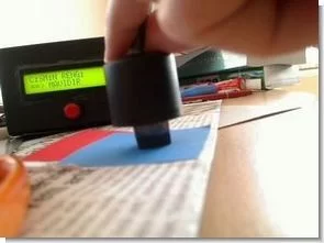
LDR CONNECTION
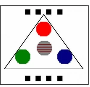
LDR as shown in the middle of three LEDs to be soldered to phenolic hole is made and resistance connections. Then close the circuit to the sensor panel of any box cover, etc .. and LEDs to close around a triangle is black colored cardboard.
NOTE: Circuit ldren in parallel to the signal cable from the LEDs if you put a value close to this value you can find. Values in this way, but I try to find the resistance less than 330Ω resistor is not in my hand was making a very small value led me hooked 🙂
Circuit of the microcontroller code “microcode Studio Plus” “PicBasic PRO” and has been compiled compiler written in. For compiling files on your computer, the compiler must PBP246 and MPASM assembly.
All files belong to the color sensor with PIC16F877 isis circuit simulation software ares pcb and source files PicBasic pro:
FILE DOWNLOAD LINK LIST ( in TXT format ): LINKS-6483.zip
Source: COLOR SENSE CIRCUIT LCD PIC16F877 PICBASIC PRO
- How does the LDR generate a signal?
The LDR placed in front of light reflected from an object generates an analog signal that enters the measurement pins of the microcontroller. - Which port is used for ADC measurement?
The signal is measured by entering through ADC PORTA.0 on the PIC16F877 microcontroller. - What software is used for circuit design?
Proteus ISIS and Proteus ARES programs are used for circuit design and printed circuit board operations. - What programming language is used for the code?
The microcontroller code is written in PicBasic Pro and compiled using Microcode Studio Plus. - How are the LEDs arranged?
The three LEDs are soldered to a phenolic hole with the LDR in the middle, and they close around a triangle of black colored cardboard. - What resistor value is recommended?
The author suggests finding a resistance less than 330Ω, though specific values may vary based on available components. - Can I simulate this circuit before building it?
Yes, the files include circuit simulation software components compatible with ISIS and ARES. - What additional tools are needed for compiling?
In addition to PBP246, the MPASM assembly tool is required for compiling the files.