
Use a C-52 EVB for simple robot experiments. Build a simple two wheels robot with L293D H-Bridge driver and IR sensors. Write a C program controls robot tracked with black tape. Fun with Ving-Peaw Competition 2543, course layout, day-by-day changed rule and scoring also included!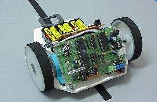
Introduction
One of my student has made a disgraceful robot that used two stepper motors and with a simple IR sensor. Yes, above picture is what I’m talking. Without battery carrying, a little bit torque of the stepper and misalignment of driving shaft, makes it crawling not walking, but first demo, showed quite impressive to me. He said he wrote a couple of program lines using C, his robot can track the black tape. I feel delighted his intention and endeavor. I thought, ” he borrowed me DS5000, expensive one, a soft uController with internal bootloader, why shouldn’t try with our learning board C-52 Evaluation Board instead”. Another one, told me the same day “I found the L293 Push/Pull Four Channel Driver at Ban-Moah, it costs 1.5 US$ “. I’ve been searching this chip for a year. The MiniBoard, a Motorola 68HC11 Robot Controller board designed by Fred G. Martin, also uses this driver. The day after, I then decided to prepare the page describing how to use C-52 EVB as a robot controller board. I asked my student for competition, build yourselves robot that can track the black tape. Prize for the winner is 100 US$, with a bit condition that the winner must pay for a big party at Soi Jinda’s Somtum (Papaya Salad) shop. And one of the competitor is me. I thought the rule should be conceived roughly by students and technically by me. The picture on that day will put here soon.
C-52 EVB resources
Beforehand, let look at available resources of C-52 EVB for robot experiments.
| Actuators | DC motor | PWM with timer2 helps | P1.4,P1.5,P1.6,P1.7 |
| Sensors | digital/analog | IR detectorwith comparator chip/ for analog input, see use of PIC16C711 | digital input/T0,T1 for pulse input |
| Brain | C program | available code and data space approx. 32kB | 8000H-FFFFH |
| Program DownloaderRunningwithout monitor | PAULMON2with PAUL’sstartup header | 9600, 8n1 | P3.0 (RxD) and P3.1 (TxD) |
DC Motor Driver
Basic circuit of using L293 forms an H-Bridge Driver is shown in Figure 1. As shown for such inductive load as DC motor, external diodes for suppressing back EMF must be connected. The MiniBoard uses L293D instead, the L293D has internal diodes, however providing a bit less driving capacity, i.e., 600mA @4.5V-36V. From the truth table, we see that direction of the motor can control by pin C and D. VINH enable/disable power to the motor, thus for speed regulation, we then use this pin for PWM signaling. See details, L293.pdf data sheet.
A circuit connecting C-52 P1 to L293 driver chip is shown in Figure 2. As shown Enable pin 1 connected to P1.0 is for PWM signaling. We use additional inverter at pin7 and pin 15 to provide proper logic for easy directional control. Please note that pin 4,5,12,13 are tied to ground and if heat sinking needed, one method is to make a large area of PCB or soldering it with a metal sheet, say.
Figure 2: Connecting C-52 EVB P1.4-P1.7 to L293. External diodes must be connected for L293(not shown in circuit diagram). My latest design put additional inverter for PWM signal at pin 1 and pin 9 to prevent full power delivering to DC motors when resetting the 89C52(i.e., all bits of P1 is logic high). Check the logic of PWM pins for another microcontrollers.
Line Tracking Sensor (I have to KUK)
Since there’s no ADC for 89C52 chip, each competitor may build their own Line Tracking Sensor, some may use LM339 QUAD comparator with IR transmitter and receiver, some may use LDR as described in Line Follower Robot . With an external comparator, it may not necessary to have ADC, but with LDR, we need external ADC. ” Having additional ADC for 89C52 would be better”, I thought. How can we provide ADC for 89C52 with a cheap method? I chose PIC16C711 with 4-channel ADC, and 7-pin input port. Interfacing to 89C52 is done with simple PISO protocol by using RB0 for SCLK and RA4 for SDA. The code for such purpose was written in C, here is the source file, C52ADC.C and the HEX code, C52ADC.HEX. After some initialization, the 711 chip wait for trigger read signal at pin RB0, i.e., high-to-low transition, then it responses by sending 40-bit through RA4(SDA) with low-to-high transition. 40-bit data stream begins with LSB of ADC0 to MSB of PORT B. Example of program fro testing ADC is ADC.C and the hex file is ADC.HEX.
For more detail: C-52EVB Robot Controller
