
Summary of USB Stepper Motor Driver using pic microcontoller
This project details a USB-controlled stepper motor driver using the PIC18F4550 microcontroller. It replaces legacy parallel port methods, allowing a PC to drive a 5-wire unipolar stepper motor (M35SP-8) via a custom USB interface board. The system relies on a C# application running on Windows to send commands through the USB 2.0 connection, which the microcontroller translates into pulse signals for the motor coils.
Parts used in the USB Stepper Motor Driver:
- PIC18F4550 microcontroller
- M35SP-8 5-wire unipolar Stepper motor
- USB Interface Board (PCB)
- C# Application (Visual Studio)
- Windows OS with USB 2.0 port
- 9V external motor supply
- LEDs for status indication
- Firmware for PIC18F4550
- Windows drivers (Win XP and Win 7)
In this project we are going to drive a unipolar Stepper motor (5 wire) using USB interface from a PC Computer. This project is an application of the USB Interface Board PIC18F4550 which was published here in the past. You can run other stepper motors too. It is simple and easy to make, we are going to use PIC18F4550 microcontroller which has an in built USB (USB 2.0) functionality which allows it to connect with any computer with a USB port and Windows OS. We will try to provide as much as details we can for achieving this project.
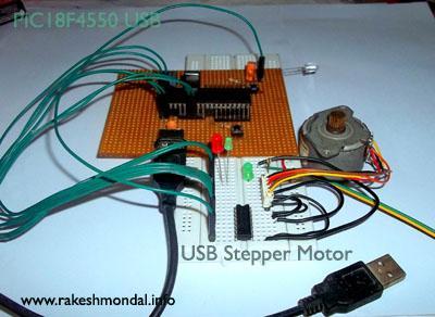 – See more at: http://www.rakeshmondal.info/USB-Stepper-Motor-Driver#sthash.J5bNPjSy.dpuf
USB Stepper Motor Driver
In this project we are going to drive a unipolar Stepper motor (5 wire) using USB interface from a PC Computer. This project is an application of the USB Interface Board PIC18F4550 which was published here in the past. You can run other stepper motors too. It is simple and easy to make, we are going to use PIC18F4550 microcontroller which has an in built USB (USB 2.0) functionality which allows it to connect with any computer with a USB port and Windows OS. We will try to provide as much as details we can for achieving this project.
OLD METHOD: The legacy (OLD) method was to use a parallel port (DB 9), which were far more easy with simple port control commands, which were good enough to glow few led directly connected to COMM pins of a parallel port, and with a simple loop written in VB it was easy to generate a pulse of blinking led for a stepper motor.
USB: However laptops and portable computers don’t come with those big D9 (parallel or printer) port anymore, as the USB ports – due to its excellent characteristics and small size has taken its replacement for almost for any external device. USB interface for this project is going to be little complex then the old parallel port method.
The microcontroller which will serve as the communication channel between the Computer and Stepper motor, the PIC18F4550 microcontroller, can work in two USB speed 12Mbps(full speed) and 1.2Mbps(low speed).
For our project we will run this microcontroller board in Full speed (12Mpbs). The project can be also achieved with a PIC18F2550 with little modification in the firmware, but since 18F4550 has more number of pins on a standard Dual Inline package (40 pins, 20 pins on each side), so we will go with that. PIC18F4550 is far more cheap and inexpensive then an Arduino board. In fact the stepper motor here costs more than the entire board and components used.
– See more at: http://www.rakeshmondal.info/USB-Stepper-Motor-Driver#sthash.J5bNPjSy.dpuf
Stepper Motor
The stepper motor used here is a 5 wire Stepper motor (M35SP-8) which is going to be operated by an application written in C#, (visual studio) which will communicate with the microcontroller board via USB, and microcontroller will drive the Motor connected with it according to the output directed by the software written in C#. The entire project and its necessary project files with schematics can be found at the end of this page.
The M35SP-8 Stepper Motor has a step angle of 7.5 degree, with one Common wire and 4 control wires connected to each coils. Hence we need only 4 control links for generating the pulse which will drive this stepper motor. For information on the specification of MS35SP-8 refer the respective datasheet.
Stepper Motor Wiring
The Figure below shows the labeling of the Stepper motor used for this project. If you wish to use any other stepper motor then you have to follow wiring labels of that respective stepper motor.
– See more at: http://www.rakeshmondal.info/USB-Stepper-Motor-Driver#sthash.J5bNPjSy.dpuf
Running other Stepper motors
The USB interface board we are using here has 6 control pins, it means you can control 6 LEDs (example) with this board. Out of which, only 4 pins are required to control our M35SP-8 Stepper motor, remaining 2 will be unused.
However you can run more kinds of stepper motor too. Since we have 6 control lines available hence the project can be easily modified to run other stepper motors too. Any stepper motor has one common ground wire and remaining are control wires, So technically with this USB interface board you can run a 5 wire, 6 wire and 7 wire stepper motor easily (6 control and one Common power).
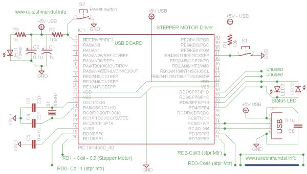
USB Interface Board Schematic
First start with the USB interface board, which will require a firmware to be loaded in the microcontroller and later, a windows driver, after the board is ready. I strongly recommend making this board on PCB.
You can find a detailed tutorial and specifications for making this board alone in my previous USB Interface post. The firmware used here is the same firmware as in PIC18F4550 board with no modification. The components required are pretty much clear in the schematic or you are free to explore USB Interface Board post for detailed component list.
After making this board, connect it with computer USB port and it would ask you for driver.
The only thing here different is the C# application, which is written for running the stepper motor.
– See more at: http://www.rakeshmondal.info/USB-Stepper-Motor-Driver#sthash.J5bNPjSy.dpuf
Connect two led across RD4 and RD5, which will display the status of the USB Board. IF the Communication between the computer and USB Board is successful then both the LED’s would blink alternatively.
The pins RD0-RD3 of the microcontroller is interfaced with 4 coils of the stepper motor, and the “Common wire” is interfaced the external 9V motor supply.
– See more at: http://www.rakeshmondal.info/USB-Stepper-Motor-Driver#sthash.J5bNPjSy.dpuf
-
What type of stepper motor is used in this project?
The project uses a 5-wire unipolar Stepper motor specifically the M35SP-8 model. -
Can this project run other types of stepper motors?
Yes, the board can easily run 5-wire, 6-wire, and 7-wire stepper motors because it has 6 control lines available. -
How does the computer communicate with the motor?
A C# application written in Visual Studio communicates with the microcontroller board via the USB interface. -
Why was the USB interface chosen over the old method?
Modern laptops lack the large D9 parallel ports, so USB was chosen due to its excellent characteristics and small size. -
What speed does the microcontroller operate at?
The PIC18F4550 runs in Full speed mode at 12Mbps for this project. -
Which pins are used to control the stepper motor coils?
Pins RD0 through RD3 of the microcontroller are interfaced with the 4 coils of the stepper motor. -
How do you verify successful communication between the PC and board?
Two LEDs connected across RD4 and RD5 will blink alternatively if communication is successful. -
Is the PIC18F2550 compatible with this project?
Yes, the project can be achieved with a PIC18F2550 but requires little modification in the firmware.
