
Summary of Breadboard module for PIC16F628A
This article describes a PIC16F628A breadboard module designed for quick prototyping, featuring built-in oscillator, reset, and ICSP circuits. Unlike the PIC16F688 version, this module uses an external 4.0 MHz crystal for accurate timing and offers full 8-bit access to PORTB. The author demonstrates its functionality by programming eight LEDs connected to PORTB using MikroC Pro and an iCP01 USB programmer.
Parts used in the Breadboard module for PIC16F628A:
- PIC16F628A microcontroller
- External 4.0 MHz crystal
- Male headers for power supply and I/O ports
- ICSP header pins
- Reset switch
- Power-on indicator LED
- Eight LEDs for testing
- 330 Ω resistors
- MikroC Pro for PIC compiler
- iCP01 USB programmer from iCircuit technology
Here’s another breadboard module that carries a PIC16F628A microcontroller. The power supply pins and the I/O ports of the PIC16F628A microcontroller are accessed through male headers. It can be easily plugged into a breadboard and is very useful for quick prototyping. It frees up a lot of space on the breadboard since the oscillator, reset, and ICSP circuits are already built on the module. It is different from the previous PIC16F688 breadboard module in the way that the microcontroller now runs with an external 4.0 MHz crystal. So, this module will be more appropriate for experiments that require accurate timing calculations. Besides, the PIC16F628a microcontroller allows you to read/write 8-bit data directly through PORTB, which is 8-bit wide (none of the ports in PIC16F688 were 8-bit wide).
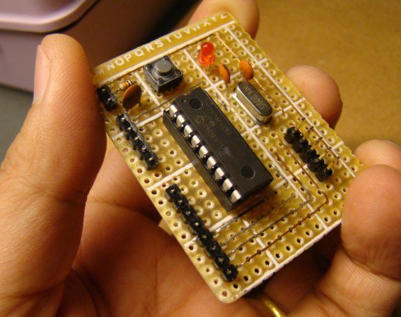
The layout and the circuit diagram of the module is shown below. The module has ICSP header pins for in-circuit programming, a reset switch, and an LED as power-on indicator. It provides easy access to all the pins of PORTB, and RA0 through RA4 pins of PORTA. Pins RA6 and RA7 are used for external crystal connections, whereas RA5 is input only pin and is used for reset circuit.
Now, the breadboard module is ready and its a time to test it. I have written a small application program to chase 8 LEDs that are connected to the PORTB pins of the PIC16F628A microcontroller. The circuit diagram is not shown here as it is very simple. The anodes of the 8 LEDs are connected to the PORTB pins, whereas the cathodes are grounded through 330 Ω resistors in series. The program is written in C and is given below. I compiled it with MikroC Pro for PIC, and loaded the HEX file into the PIC16F628A microcontroller with my handy iCP01 USB programmer from iCircuit technology. In the configuration bit settings, MCLR should be enabled and the clock source could be XT or HS, both will work for 4.0 MHz.
For more detail: Breadboard module for PIC16F628A
- What makes this module different from the previous PIC16F688 breadboard module?
This module uses an external 4.0 MHz crystal for accurate timing calculations and allows direct read/write of 8-bit data through PORTB. - How can I program the PIC16F628A on this module?
You can use the ICSP header pins with a programmer like the iCP01 USB programmer to load the HEX file. - Which pins are accessible on this breadboard module?
The module provides easy access to all PORTB pins, RA0 through RA4 of PORTA, while RA5 is for reset and RA6/RA7 are for the crystal. - Can I use XT or HS clock source settings for this module?
Yes, both XT and HS configuration bit settings will work for the 4.0 MHz external crystal. - How should the test LEDs be connected to the module?
The anodes connect to PORTB pins, and the cathodes are grounded through 330 Ω resistors in series. - What software was used to compile the application program?
The program was written in C and compiled using MikroC Pro for PIC. - Why is this module suitable for experiments requiring accurate timing?
It runs with an external 4.0 MHz crystal, unlike the internal oscillator options found in other modules. - Is the RA5 pin available for general input/output?
No, RA5 is an input-only pin specifically used for the reset circuit.
