Summary of PIC programmers for parallel port
This article details the UNIPROG V-A, a parallel port programmer for PIC microcontrollers and EEPROMs. It presents three design variations: one using a 4066 chip, another with PNP transistors, and a third by H. Schaer. The guide includes PCB layouts, schematics, and specific component lists for each version. It also outlines configuration tables (A through J) to support various chip combinations, including single or dual PICs and multiple EEPROMs, utilizing switches and sockets for flexible programming modes.
Parts used in the UNIPROG V-A:
- ISO card slot
- Female Centronix connector 36pin
- 74LS06 or 74LS07
- 4066
- 7805 voltage regulator
- 7812 voltage regulator
- PNP transistor BC557
- 1N4001 diode
- 1N4148 diode
- Green LED
- Red LED
- Capacitor 10-47u/25-63V
- Capacitor 100nF
- Capacitor 1nF
- Resistor 100R
- Resistor 1K0 or 1K2
- Resistor 10K
- Resistor 18K
- Resistor 4K7
- Single switch on-on
- Double switch on-on
- Socket 8pin
- Socket 18pin
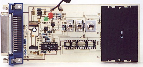
uni5_a.bmp – PCB of parallel programmer UNIPROG V-A
uni5_as1.bmp – schematic diagram of G.Tait’s programmer with 4066
uni5_ao1.bmp – layout of components of G.Tait’s programmer with 4066
 List of components:
1 x slot for ISO card (eight pins are enough)
1 x female Centronix connector 36pin
1 x 74LS06 (7406) or 74LS07 (7407)
1 x 4066
1 x 7805 (78L05)
1 x 7812
1 x 1N4001 D1
2 x 1N4001 (1N4148) D2,D3
1 x LED green
1 x LED red
1 x capacitor 10-47u/25-63V
5 x capacitor 100nF
2 x capacitor 1nF
2 x resistor 100R
2 x resistor 1K0 (1K2)
5 x resistor 10K
2 x resistor 18K
2 x single switch on-on
1 x double switch on-on
1 x socket 8pin
1 x socket 18pin
Programmer by D. Tait with PNP trans.
uni5_a.bmp – PCB of parallel programmer UNIPROG V-A
uni5_as2.bmp – schematic diagram of G.Tait’s programmer with PNP trans.
uni5_ao2.bmp – layout of components of G.Tait’s programmer with PNP trans.
List of components:
1 x slot for ISO card (eight pins are enough)
1 x female Centronix connector 36pin
1 x 74LS06 (7406) or 74LS07 (7407)
1 x 7805 (78L05)
1 x 7812
2 x PNP transistor (BC557)
1 x 1N4001 D1
2 x 1N4001 (1N4148) D2,D3
1 x LED green
1 x LED red
1 x capacitor 10-47u/25-63V
5 x capacitor 100nF
2 x capacitor 1nF
2 x resistor 100R
2 x resistor 1K0 (1K2)
2 x resistor 4K7
7 x resistor 10K
2 x single switch on-on
1 x double switch on-on
1 x socket 8pin
1 x socket 18pin
Programmer by H. Schaer
uni5_a.bmp – PCB of parallel programmer UNIPROG V-A
uni5_as3.bmp – schematic diagram of H.Schaer’s programmer
uni5_ao3.bmp – layout of components of H.Schaer’s programmer
| Type | Chips | SW1 PR1 |
SW2 PR2 |
SW3 PR3 |
| A. 1xPIC (RB7) – single PIC card | SLAVE(RB7) | A | A | A |
| B. 1xPIC (RB6) – single PIC card | MASTER(RB6) | A | A | B |
| C. 1xPIC (RB7), 1xEEPROM – Multimac II | EEPROM SLAVE(RB7) |
B A |
B A |
B A |
| D. 2xPIC (RB6, RB7) – twine PIC card | MASTER(RB6) SLAVE(RB7) |
A A |
A A |
B A |
| E. 2xPIC (RB6, RB7), 1xEEPROM – quadra | EEPROM1 MASTER(RB6) SLAVE(RB7) |
B A A |
B A A |
B B A |
| F. 2xPIC (RB6, RB7), 2xEEPROM – quadra
Attention! EEPROM2 can be programmed only in a socket! |
EEPROM1 MASTER(RB6) SLAVE(RB7) EEPROM2 |
B A A – |
B A A – |
B B A – |
| G. 1xPIC(RB7) – wafer card | PIC | A | A | A |
| H.1xPIC(RB7), 1xEEPROM – MM2 wafer card | EEPROM PIC |
B A |
B A |
B A |
| J. 1xPIC(RB7), 1xEEPROM – gold MM2 wafer card use Phoenix interface for EEPROM |
PIC
EEPROM |
A
– |
A
– |
A
– |
List of components:
1 x slot for ISO card (eight pins are enough)
1 x female Centronix connector 36pin
1 x 74LS06 (7406) or 74LS07 (7407)
1 x 7805 (78L05)
1 x 7812
2 x PNP transistor (BC557)
1 x 1N4001 D1
2 x 1N4001 (1N4148) D2,D3
1 x LED green
1 x LED red
1 x capacitor 10-47u/25-63V
4 x capacitor 100nF
2 x resistor 1K0 (1K2)
10 x resistor 10K
2 x single switch on-on
1 x double switch on-on
1 x socket 8pin
1 x socket 18pin
For more detail: PIC programmers for parallel port
- What components are required for the G.Tait programmer with 4066?
The list includes an ISO card slot, 36pin Centronix connector, 74LS06 or 74LS07, 4066, 7805, 7812, diodes, LEDs, capacitors, resistors, switches, and sockets. - How does the PNP transistor version differ from the 4066 version?
The PNP version replaces the 4066 chip with two PNP transistors like BC557 and adjusts resistor counts while keeping other core components similar. - Can this programmer handle multiple PIC chips simultaneously?
Yes, configurations D, E, and F support two PIC chips using RB6 and RB7 pins for master and slave operations. - Does the quadra configuration allow programming of two EEPROMs?
Yes, but the article notes that EEPROM2 can be programmed only in a socket. - What is the best way to configure the programmer for a single PIC card?
Use configuration A for RB7 slave mode or configuration B for RB6 master mode depending on the specific requirement. - Are there specific resistor values needed for the H.Schaer programmer?
The component list specifies 2 x 1K0, 10 x 10K, and various capacitors, though exact resistor counts vary slightly from the PNP version. - Can the wafer card configuration program both PIC and EEPROM?
Yes, configurations G, H, and J support single PIC cards with or without EEPROMs. - What interface is recommended for the gold MM2 wafer card EEPROM?
The article states to use the Phoenix interface for EEPROM in the gold MM2 wafer card configuration.