Summary of Barcode Scanner
Summary: They built a barcode scanner using an OV7670 CMOS camera, a PIC32MX250F128B microcontroller, and an ESP8266 Wi-Fi module. The system captures black/white bar patterns, compresses pixel data to fit PIC32 memory, decodes bar sequences into binary, displays results on a TFT, and sends decoded data over Wi-Fi to a web page hosted by the ESP8266. Key challenges included SCCB vs I2C configuration differences, pin limitations, PCLK slowing, and aggressive bit-level compression for memory constraints.
Parts used in the Barcode Scanner:
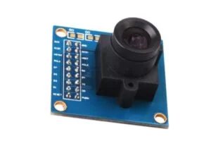
- OV7670 CMOS camera module
- PIC32MX250F128B microcontroller (PIC32)
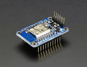
- ESP8266 Wi-Fi breakout (Adafruit)
- TFT display
- Raspberry Pi (used as hotspot)
- Pull-up resistors (5K) for SIO_C and SIO_D
- Wiring and connectors (for UART, I2C/SCCB, power, grounds)
- Power supply (3.0V for camera and appropriate supplies for other parts)
- Buttons (Decoding/Display button)
Introduction
In our final project, we used CMOS camera to identify interval binary 0 and 1 sequence represented by black and white bars. Then, we used WIFI module to transmit the sequence to personal computer and displayed it on a web page.
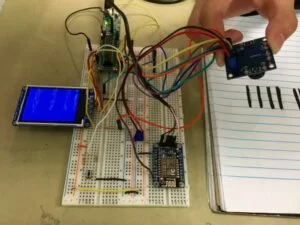
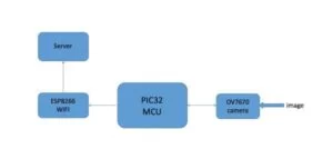
In our projects, we chose OV7670 CMOS camera and ESP8266 WIFI module for image capture and WIFI transmission. Since PIC32MX250F128B only has 32K bytes inside memory and a low CPU frequency compared to the large data scale of image, we did data compression and data processing in order to match the PIC32 with OV7670. What is more, we did some adjustment to I2C transmission in order to configure the camera which originally used a SCCB (Serial Camera Control Bus) to set up.
For WIFI part, we used UART to connect the microcontroller and WIFI module. Since Cornell campus WIFI is not proper to use for a WIFI module, we set a raspberry pi as a hotspot.
High Level Design
Rationale and Source of Our Project Idea
What does “microcontroller” mean? It means “control”. The reason we used microcontroller was to control different peripheral devices. OV7670 CMOS camera is a popular CMOS camera and has been widely used. However, there is little information about using OV7670 on PIC. So we thought it would be very cool to build the connection between OV7670 and PIC. What is more, in lab4, we have built the wired connection between the personal computer and PIC by USB wire so we wanted to build the wireless connection by WIFI in our final project.
In addition, nowadays, the barcode is widely used. As is known to all, the barcode consists only black and white bars which can be easily represented by binary 0 and 1. The simple representation of barcode is proper to the PIC32 which only has 32K Bytes memory.
Background Information
RGB Color Model[1]
The RGB color model is an additive color model in which red, green, and blue light are added together in various ways to reproduce a broad array of colors. The name of the model comes from the initials of the three additive primary colors, red, green, and blue. The main purpose of the RGB color model is for the sensing, representation, and display of images in electronic systems, such as televisions and computers.
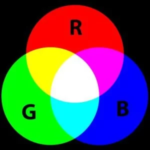
The RGB model consists of three parameters. Each of them has a range of 0 to 255. When all three parameters are 255, it displays pure white. On the other hand, when they are all 0, it shows pure black. Our identification of black and white is based on this.
Logical Structure
Hardware and Software Tradeoffs
OV7670
The OV7670 CMOS camera is a widely used electronic part so there is a great amount of information about its configuration. Although there is few open source code of its configuration on PIC, the open codes on other devices can provide enough information about registers for us. What is more, Ruochen has experience on using this camera on FPGA. The second big advantage is its price. Compared with the expensive 30 bucks serial camera, it is only about 10$. This is a good news for our budget. Every Coin has two sides. This camera also has some shortcomings which we were fully aware of before we began our project. The first one is that OV7670 only has parallel output which means when sending data to the PIC, it will occupied a huge number of pins. However, according to our specific need to identify black and white, we figured out a good method to use as few pins as possible. This method will be discussed in the following parts. The second one is that although OV7670 is a popular part, there is no often used on PIC. According to our pre-research, there is little information about connection between OV7670 and PIC.
ESP8266
The ESP8266 is also a widely used WIFI model and is also a Aruino-friendly device. It can use UART to communicate with PIC which makes it easier for us to apply. The disadvantage of this part is that the older version chip production has been stopped and the there is no new datasheet for the new one.
Standards
IEEE 802.11[2]
IEEE 802.11 is a set of media access control (MAC) and physical layer (PHY) specifications for implementing wireless local area network (WLAN) computer communication in the 2.4, 3.6, 5, and 60 GHz frequency bands. They are created and maintained by the IEEE LAN/MAN Standards Committee (IEEE 802).
SCCB[3]
SCCB (Serial Camera Control Bus) is a protocol defined and deployed by OmniVision Technologies Inc. for control of most of the functions in the OmniVision’s family of CAMERACHIPTM sensors.
Hardware
Image Capture
In our project, we used OV7670 as the image sensor. This camera had at least 8 pins which must be connected.
1.VDD: uses a 3.0V power source.
2.GND
3.SIO_C: receives clock signal from the microcontroller for SCCB
4.SIO_D: SCCB input and output
5.HERF: row signal of each frame. When HERF is high, the camera is transmitting one row of data.
6.VSYNC: frame signal. When VSYNC is low, the camera is transmitting one frame of data.
7.XCLK: receives external clock from the microcontroller used by the camera for data transmission.
8. PCLK: clock signal produced by the camera for transmission. This clock can be produced by prescaling the XCLK. Each rising edge of PCLK represents sending one byte data and the falling edge is the end of one byte.
The OV7670 has many working modes and it is very significant to choose proper modes.
First, the OV7670 has many color output format, for instance, RGB565/555/444, YUV(4:2:2) and YCbCr(4:2:2). At first, we decided to use the YUV output format because the “Y” parameter is the grayscale value of a pixel. It seemed reasonable to use grayscale to identify black and white. However, according to our research and experiment, the “grayscale” is more like a parameter of luminance which means that it can be easily influenced by light. So we turned to RGB output format and chose RGB444.
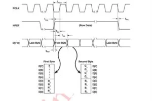
In this format, every frame needs 2 bytes and each parameter occupies 4 bits. Since the OV7670 is parallel output, the output needs 8 pins which is too many for the little PIC. Fortunately, we used a trick here. All we needed to do was distinguishing between black and white so all we needed was just a threshold. That meant the actually number of pins might be smaller than 8. For example, in our RGB444 case, if we want to set the threshold at 128, which is the half of RGB range, we just needed the top bit of the 4 bits of one parameter. If this bit is 1, it means that the value is larger/equal than 128. If it is 0, the value is smaller than 128.
To get a proper threshold, we have done many experiments. In these experiments, we found that when one pixel was black,the output RGB value was close to 256 instead of 0. And the smaller the threshold is, the more the image would be influenced by shadow. So we set the threshold at 192. In addition, we also found that using one parameter to recognize almost had the same result as using all three parameters. As a result, we only used R parameter in our project. Combining both aspect, we only needed D3 and D2 output pins on the camera.
Second, the camera has several image size output mode including VGA(640*320), QVGA(320*240), CIF(352*288), QCIF(176*144). However, the PIC32MX250F128B only has 32K bytes memory. Even if we use QCIF (176*144) and output mode, which is the smallest output mode, and RGB444 output mode, storing one frame image still needs 176*144*2=50.688K byte, far more than the memory which the PIC has. We solved this problem in software part which we will talk about later. In our project, we chose QVGA mode.
Third, the default frequency of PCLK is equal to the XCLK from PIC, in this project, was 40MHz. Considering the large data stream from the camera to the PIC and the time of data processing, the CPU frequency of PIC was not fast enough so we needed to slow down the PCLK in order to give the PIC enough time. The Largest prescaler of the camera was 128 so we chose this mode.
Data Uploading
We used an ESP8266 Wi-Fi breakout to upload the result to a server, which is set by the shield itself in order to give the access of the result to any devices that can connect to the local network. In this way, the result could be seen remotely and could acquire more computing sources for the further decoding from devices like PCs or smartphones.
The ESP8266 Wi-Fi shield from Adafruit has two UART ports for data transmission and offers a complete and self-contained Wi-Fi networking solution allowing it to host the application itself without external clock or storage. The ESP8266 processor is an 80 MHz microcontroller with a full Wi-Fi front-end (both as client and access point) and TCP/IP stack with DNS support as well. We transmitted the data from the PIC32 to the ESP8266 Wi-Fi breakout via UART port by simply wiring the TX port of the PIC32 to the RX port of the ESP8266, and ground the two GND pins together.
Pin Management
In addition, nowadays, the barcode is widely used. As is known to all, the barcode consists only black and white bars which can be easily represented by binary 0 and 1. The simple representation of barcode is proper to the PIC32 which only has 32K Bytes memory.
The most important issue we considered before we started was pin management. Since PIC only had 28 pins and the number of pins we could use was just 21. The OV7670 had 18 pins and the number we must connected was 8. These pins were VDD, GND, SIO_C, SIO_D, VSYNC, HERF, XLCK, PCLK. Fortunately, for the data transmission, we only needed the top bit of one byte because we treated R parameter more than 128 as white, less than 128 as black. What is more, for the communication with WIFI module, since we only needed to write to it, we just used one pin for UART transmission. The detailed pin management is shown below.
TFT
Pin3: MOSI (SDO1)
Pin4: D/C
Pin5: CS
Pin6: RST
Pin25: SCK1
OV7670
Pin9: Decoding/Display Button
Pin10: connected to XCLK, provided peripheral clock for the camera
Pin12: connected to HERF, received row signal from the camera
Pin14: connected to D3 output, read the top bit of RED in RGB444 output mode
Pin16: connected to PCLK, received byte signal from the camera
Pin17: connected to SIO_C, provided I2C clock for the camera, used a 5K resistor to pull up
Pin18: connected to SIO_D, wrote configuration message to the camera, used a 5K resistor to pull up
Pin24: connected to VSYNC, received frame signal from the camera
ESP8266
Pin21: UART transmission
Software
Overview
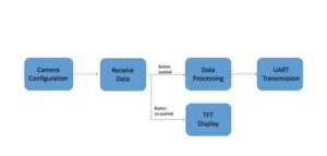
The software of the project consists of four parts, camera configuration, data capture and processing, decoding and display, WIFI transmission. First three parts are based on PIC and WIFI part is on WIFI model.
Compared with the CPU frequency of PIC, the data transmission speed was fast, so we needed to give PIC enough time to do data processing. Taking this into consideration, pt_thread and interrupt were too slow. As a result, we did not use pt_thread or interrupt in our program. All the code were in main function.
Camera Configuration
According to our pre-research, most of opinions on the Internet think that the SCCB is almost the same as I2C and some people even say that SCCB is just another name of I2C used by OmniVision. However, after reading the datasheet of SCCB and some experiment on our own, we found that there are many huge differences between these two protocols. The biggest difference in our application is that in I2C, in both writing or reading, after sending the I2C device address byte to the slave with a write indication, the master has to wait for and verify an Acknowledgement from the slave. Only after receiving and verifying this Acknowledgement, the master can send the slave the address of specific register.
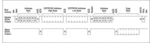
However, according to the SCCB protocol, in writing mode, after the master send the one byte address to the slave, the ninth bit is “Don’t care” which means that the master does not need an Acknowledgement.
This means that if we use I2C to do the configuration of SCCB, after PIC sending the I2C device address the the camera, it will not receive an Acknowledge from the camera so the transmission will be blocked. In order to solve this, we let the I2C not wait for the Acknowledge. All it needs to do is to write message to the camera. In this way, we successfully set up the camera. The goal of configuration is to let the camera work at different mode. In order to realize the function we needed, we chose to set up these following modes.
1. QVGA Output The default output mode of the camera is VGA which is 640*480. Taking the memory scale of PIC into consideration, it is to large for the PIC. So we decided to use QVGA mode which is only ¼ of VGA.
2. 128 Division PCLK The default frequency of PCLK is equal to the XCLK from PIC, in this project, is 40MHz. Considering the large data stream from the camera to the PIC, the CPU frequency of PIC is not fast enough so we need to slow down the PCLK in order to give the PIC enough time to process the data. The Largest prescaler of the camera is 128 so we chose this mode.
3. RGB 444 Output
4. AWB Closed
Data Capture and Processing
The image size of RGB444 is 320*240. If we directly used the original data from D3 and D2, storing one frame needed 320*240*2 = 153.6K bytes. So we had to do some data compressing before the PIC stored the pixel information. When both two reading pins were high, we treated the current pixel as black. So we put a “1” into the data array. Or we put a “0” into the data array.
However, since the smallest type of data is char which is one byte, this compression was still not enough (320*240 =76.8K), this compression was still not enough (320*240/1000=76.8K). So we shifted every byte to use the storage more efficiently. We had a two dimensional array of 40*240. For example, once we received a “1” of a pixel from the camera, we did the “|1”operation to the current byte and then we did one-bit left shift to this byte. If we received a “0”, we just did the shift operation. After we received 8 bit, we took a new byte from array to store data. In this way, we only needed 9.6K bytes to store one pixel, only 30% of the total memory. And we compressed the original data by 16 times.
Decoding and Display
When data of one pixel was received completely, the program went into Decoding and Display process. In this process, we had two separately functions, decoding and display. Whether the program went into decoding function or display function decided by the transmission button connected to the PIC.
When the button was pushed, the PIC went into decoding mode. In order to simplify the decoding process, we just took the middle row of the picture. First, we tried the first black bar. Once we found the first black bar, it meant that the information appeared. Then we began to find the white bar. In order to eliminate noises, we treated at least 6 continuous white pixels as the appearance of white bar. What is more, every time we identified a color, we put a 0 or 1 into the array.
After the recognition, we transmitted the sequence by UART to the WIFI module.
When the button was unpushed, the PIC displayed the image on the TFT. The display was just like the inverse process of data processing. We used right shift operation to take out data of each pixel and display it on the TFT.
Data Uploading
When the data transmitted from the PIC32 via UART, it will go into a buffer in the ESP8266 WIFI shield waiting to be read. The ESP8266 WIFI breakout from Adafruit can be programmed using the Arduino IDE. The state of the buffer can be check through the software using the <SPI.h> library, so if there are data in the buffer, the state of the buffer will be seen as “available” in the code.
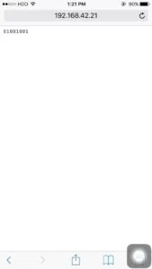
We used the build in library <ESP8266WiFi.h>, also provided by Arduino, to connect the WIFI breakout to a WIFI network and set the server based on its IP address. To upload the data to the server, we first connected the ESP8266 WIFI breakout to the local network and print out its IP address when the connection was set. The IP address is the web address we use to see the result, in this case was 192.168.42.1, a local IP.
When the WIFI connection was set, we kept reading the data that had been send from the PIC32 and stored in the local buffer using a loop until it read a ‘\n’ character when the data is available. After the reading was done, we start a server and print the data on the server. The uploading should keep running even if there is no new data input via the UART from the PIC32 to keep the server accessible all the time. Otherwise the server can only be accessed the moment when the ESP8266 is uploading the latest data.
When the uploading was done, we could see the result from any electronic device that is in the same local network by simply accessing a web page.
Results
Safety
Considering the goal of our project, the barcode scanner we made did no harm to human and environment. In our project, we paid attention to electrical safety including using power supply safely and not burning our electronic parts.
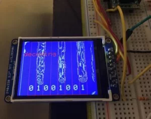
Accuracy
According to the picture, we can easily recognize the black bars on the paper. However, as we can see in the Fig.10, the black bar was not fully “filled” like we drew on paper, which means that there were something inaccurate happened either in the image capture part or in the data compression part, or even in both. Since we did data compression and data processing before we displayed the image on the TFT, we were unable to figure out where the inaccuracy exactly happened. And what’ more, according to our experiments, we found that the image we display on the TFT screen was easily influenced by the light and shadow.
Due to the accuracy of the OV7670 camera, the bar code scanner we built can only identify eight black-and-white bars accurately right now. But if the scanner wants to identify as many bars as a real bar code has, the accuracy still needs to be improved.
The accuracy of WIFI transmission is 100%. What we could get on the devices like PC and cell phone was exactly the decoding result shown on the TFT. And after pushing the decoding button, we could get the decoding result immediately.
Conclusions
Results vs. Expectations
Except for the accuracy, we achieved almost all the goals as we expected, including:
1. Configured the OV7670 camera clock frequency and image size using I2C protocol.
2. Capture the image data using PIC32 according to the output signal from the OV7670 camera.
3. Compressed the image data into black and white to fit the memory size of PIC32.
4. Displayed the black-and-white image on the tft screen for debugging and monitoring.
5. Decoded the image data into the state of bars represented by 0 and 1.
6. Transmitted the result to the ESP8266 Wi-Fi breakout through UART.
7. Uploaded the data to a server that can be access by any electronic device in the same local network.
But there are still some parts of the project need further improving:
1. Due the memory size of OV7670, we were unable to see the original image captured by the OV7670 through the screen, which heavily impact the accuracy of the project since we had no other way to know how to adjust the camera’s focal distance to make the image clearer to be recognized.
2. The image compression method was kind of rough by just selecting one bit from the RGB444 image data format to represent the black-and-white state of the pixel.
3. The result sent to the server can only accessed by the devices in the same local network. It will be better if it could be accessed through the worldwide Internet.
Future Changes
For further improvements, the image should be displayed on a screen directly instead of after roughly compression to get more accuracy. To achieve this, the PIC32 needs an extra memory to store the image data. But also this may slow down the system.
There are many registers in the OV7670 camera that can be configured to get the image effects a user wants. If the original image can be seen directly through a screen, then we could try to configure some more registers to improve the image quality to let it fit the project demands better.
Works on the ESP8266 Wi-Fi breakout can be improved by looking for other ways to program it instead of using the exist library provided by Arduino. In this way, the functions of this Wi-Fi shield could be largely extended to set a better server.
Intellectual Property Considerations
The hardware parts were all derived from several sources and the hardware connection was all completed by ourselves. When using these parts, we referred to several datasheets which we have listed in reference part of our report.
For software part, the “main.c” realizing the main functions was all written by us. And the header files and source files including libraries, configuration, TFT display helper functions[4] and PT thread[5] were from lab4 of ECE4760 class and written by Bruce Land and Syed Tahmid Mahbub.
Ethical Considerations
Our project adheres to the IEEE Code of Ethics. In our project, we did not use any material or parts which may do harm to human. Our device cannot be used as a weapon or something else that may hurt people.
The final goal of our project is to make people’s life easier and more convenient. The barcode is widely used nowadays and we hope that our device and experience can help people use barcodes easier.
In this project, we also want to have a deeper understanding of all parts we have used. We hope that our experience can help other fellows use OV7670 and ESP8266 on PIC32. We are very willing to share our own codes with all the people. We are also happy to accept and offer honest criticism and advice from others. All groups in ECE4760 class have done a good job in the final project and we are very proud of taking this great class.
We certify that all work which we state as independent work is all done by ourselves. All references of datasheets, figures, etc. have been listed in reference part of our report.
Legal Considerations
Our project does not violate any legal consideration. All pictures and diagrams without a reference are drawn by ourselves. All references we have used have be indicated. All materials used were purchased by us or taken from lab with permission.
Acknowledgements
We would like to thank our instructor, Bruce Land. He has given us great help throughout our final project and the course. He is a great scientist and also a good friend. We also want to thank our TAs, Victor, Manu, Shiva, Tahmid and Taylor. They have helped us a lot in our assignments and final project.
Source: Barcode Scanner
- What camera was used to capture images?
The OV7670 CMOS camera was used for image capture in RGB444 mode. - How did the team connect the camera to the PIC32 given SCCB differences?
They used I2C but modified it to not wait for an ACK so the SCCB-style writes from the camera would not block transmission. - Can the PIC32 store full frames from the OV7670?
No, the PIC32 32K memory is insufficient, so they compressed image data by packing bits into bytes, reducing storage by 16 times. - How did they reduce the number of camera data pins used?
They only read the top bit of the R parameter in RGB444 (using D3 and D2) since a threshold on one channel was sufficient to distinguish black and white. - How is data transmitted from PIC32 to the web page?
The PIC32 sends decoded binary via UART to the ESP8266, which hosts a server and displays results accessible on the local network. - What mode and settings were chosen for the OV7670?
They chose QVGA output, RGB444 format, PCLK prescaled by 128, and closed AWB. - Does the system display images locally?
Yes, when not in decoding mode the PIC displays the compressed black-and-white image on a TFT for debugging and monitoring. - How accurate is the barcode recognition?
It can accurately identify eight black-and-white bars; overall accuracy is affected by lighting, compression, and image quality limitations. - How reliable is the Wi-Fi transmission?
The Wi-Fi transmission accuracy is reported as 100%; devices on the same local network see exactly the decoded result. - Why was a Raspberry Pi used in the setup?
The Raspberry Pi was used as a hotspot because the campus Wi-Fi was not suitable for the ESP8266 module.