This is my first instructable.So plz comment and help me out with any mistakes i might commit .
I have created a pcb for avr 32 ,its a development board .I saw that there none online with pcb that could be done at home so thought y not put it.
To start with u need the basic concept of printing pcbs and itching them .
i find this link easy to learn http://www.riccibitti.com/pcb/pcb.htm.
And iam using eagle to create my pcb , an i think it can be improved .
Components Required
1. DC jack
2. 2amp bridge(KBP206g)or similare
3. push switch for power
4. cap(1000uf ,22pf-2)
5. regulators(7812,7805)
6. botton for reset
7. lot of male pins and female pins
8. 40pin dip socket or zip socket
9. led
10. resistor (100ohm, 1kohm)
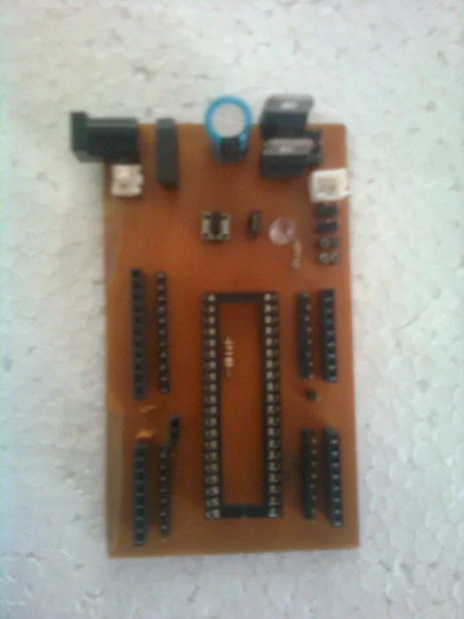
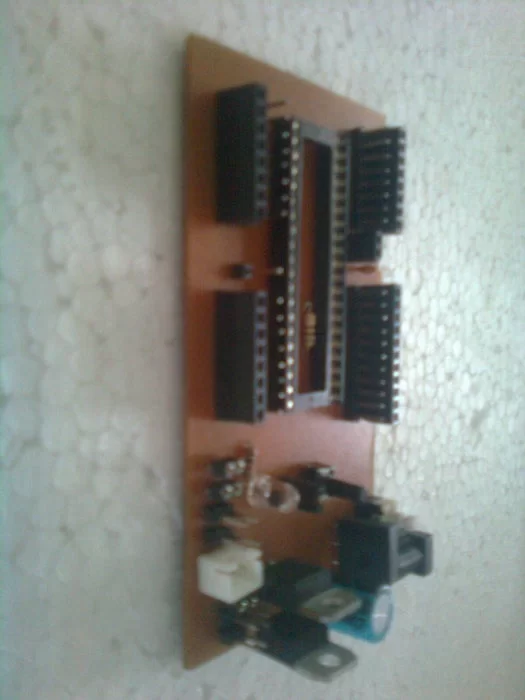
bellow are pictures of the completed board.
Step 1:
Lets get started
first to develop the board on eagle . That i have already done .
the one in the pictures is little diff from the one i put in eagle,i made some changes after a found some more requirements.
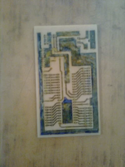
below is the pic of how the board looks on eagle.
i have uploaded the eagle .brb file which shows the complete details, and also a pdf file which can directly be printed.Be carefull while printing,see that the size is not altered and compare i.e. try placing components on printed paper before ironing it on to the board.
Attachments
Step 2:
Now for making the pcb.
once u have printed the sheet to size on a magazine sheet,we have to transfer on to a copper clad.
For full help see this cite http://www.riccibitti.com/pcb/pcb.htm
Now i assume u know how to do that and u have ironed and etched the board as well.
now drill holes and rite positions ,it would help if u kept the image on screen (eagle file)while u do the drill it sure helps me.
i have put as many pics as i could to show how the board looks like.
and sry for the bad images dont have a good camera:(
Step 3:
Now the board is ready to get all its components.
As shown in eagle the value of all the components are given which u can use for reference during soldering.
iam sry but the BOARD in the PIC IS SLITLY DIFF FORM WAT I GAVE ON EAGLE.
dont get confussed, i have just moved the regulators(7812and7805)so that u could add heat sinks if required and also added extra male pins so u could connect more peripheral boards.ill try putting new pics if i can .
The board is now complete. just add a avr 32 or 16 to it and enjoy using it.
any doubts plz comment and help me out with any problems that i might have done with out knowing
Source: AVR32 Development Board at Home