Summary of Automated Resistor Sorter with GUI
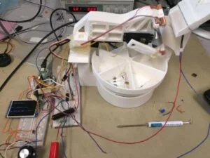
Our team built an automated resistor sorter: a 3D-printed mechanical system driven by a PIC32 that feeds, measures (CTMU autoranging), and sorts resistors into bins via a servo, stepper motor, and solenoid, controlled through a simple TFT GUI navigated with a 10-turn potentiometer and a select button. Calibration and software state machines improve measurement accuracy; main limitations are mechanical feed reliability. The design is modular, printable, and intended as a basis for a lab-assist product.
Parts used in the Automated Resistor Sorter:
- 3D printed Base
- 3D printed Spinner (6-section wheel)
- 3D printed Measurement Servo Holder
- 3D printed Measurement Arm
- 3D printed Feed Mount
- 3D printed Feed Slide - In
- 3D printed Feed Slide - Out
- 3D printed Feed Plunger
- Futaba S3003 Servo motor
- PF35T-48L4 Stepper motor
- ULN2003A driver chip (for stepper)
- Adafruit Mini Solenoid
- Power NMOSFET (solenoid driver)
- Power resistor (in series with solenoid)
- Flyback diode (for solenoid)
- Conductive copper tape electrical contacts
- 10-turn potentiometer
- Push button switch (with 10k Ohm pull-down resistor)
- PIC32 microcontroller (with CTMU and ADC)
- TFT display (GUI)
- Wiring, solder, and hot glue for assembly
Introduction
Our project is a resistor sorter that allows users to input multiple resistors, measure their resistance, and sort them into predefined bins or return them to the user. For a video of our sorter, please see our Project Demo.
From the onset, we wanted to make a project that approached a realizable product where users can input multiple resistors and easily have them sorted for them. The project involved coordinating physical hardware with motor controllers and a user interface. We implemented the mechanical hardware via 3D printed polylactic acid (PLA) plastic for low cost and the rapid iteration on designs. To control the physical constructions, a servo, stepper motor, and solenoid are controlled via the PIC32 and drive transistors to allow the resistors to be sorted. Finally, the user interface allows easy and intuitive interaction with the system. These three sections culminate in a design that provides a basis for a potential product providing basic laboratory assistance.
Contents
- High Level Design: Explanation of our project origins and structure.
- Hardware: Physical parts of our project.
- Software: Software implementation of our project.
- Results: Quantitative and qualitative performance analysis.
- Conclusion: Discussion of project implications.
- Appendices: Additional files.
High Level Design
Rationale
We wanted a novel project that could be used in the laboratory to improve the lab in some way. The resistor sorter was determined to be a project that had not been done before, with suitably difficult hurdles, and a meaningful/useful impact.
Background Math
The most basic background for measuring resistance is simply to apply Ohm’s law, V=IR, to the resistor, given a known voltage or current, and then measuring the other. The resistance can then be calculated as R = V/I. It is important to note that we simply cannot apply any voltage or current that we wish to an unknown resistor. If we apply a large voltage to a small resistor, we could potentially exceed the 15mA maximum that can be sourced from a port pin on the PIC32.[3] If we supply too large a current to a large resistor, we will exceed the voltage values the microcontroller can read or the maximum power dissipation (P = I2R) of the resistor. Thus, we have implemented an autorange feature using the Charge Time Measurement Unit (CTMU) current source to adjust the current gradually upward.
Logical Structure
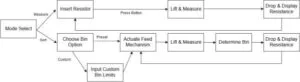
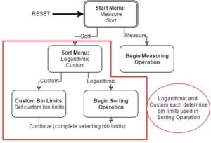
Measuring a resistor using our resistor sorter consists of the following actions, Detailed in Figure 3:
- Mode Selection – Choose mode of operation and, if applicable, input the custom bin limits.
- Feed Resistor – Activate the solenoid and feed a resistor from the feed queue to the measurement arm.
- Measurement – Lift the resistor on to the contacts, pass a test current across the resistor using the CTMU current source, measure the voltage, and calculate the resistor value
- Sorting – Determine the appropriate bin for the resistor based on the value, rotate to and drop the resistor into the bin, and appropriately reset the arm for feeding again.
Hardware & Software Tradeoffs
For the most part, our final project was a highly mechanical task and thus could only be accomplished using hardware for tasks such as rotating bins, feeding resistors, and the mechanical sorting arm. The main tradeoffs were in determining user interaction with the sorter. We decided on a predominantly software based GUI instead of an array of switches to allow greater customization of bins and use with few inputs.
We had multiple sensors available including different pushbuttons and potentiometers, so different implementations were possible. The final design, a 10-turn potentiometer and one select button, was decided by the need for an ability to choose a value between 1 and 1000 with a degree of accuracy. Linearly interpolating a 10-turn potentiometer seemed the simplest, hassle free method of implementation. This removed the option for selection buttons (akin to a directional pad) or a potentiometer with fewer turns. Furthermore, we planned to include only one button (the select button) to simplify operation.
To navigate menus with a 10-turn potentiometer, thresholding would be too tedious. In keeping the number of input devices low, more buttons were also not an option. Therefore, for navigation, the derivative of the potentiometer’s change is recorded. This directional value determines the selection bar’s movement. Also, the edge values of the potentiometer are hard coded into the GUI. These will always display their corresponding edge case, to prevent a user being at the potentiometer’s limit and unable to move towards the selection they desire.
Applicable Standards
There are two notable standards that apply to our design. The first is IEEE Standard 118-1978, “For Resistance Measurement” [10]. This standard outlines different approaches for measuring the resistance of a circuit component, based on that component’s approximate resistance and the precision of measurement desired. In particular, the standard outlines a number of bridge circuits that could be used for high precision measurement of resistors Since most lab resistors have 5% tolerance, a low precision approach is sufficient for this application. In particular, the Voltmeter-Ammeter approach described in section 4.1.1 was chosen.
The Second notable standard that applied to our design is ISO 9241, “Ergonomics of Human-System Interaction.” Since our design was to contain a user interface, we wanted this user interface to be as easy to understand as possible. Unfortunately, this standard is behind a significant paywall and is not accessible through Cornell resources, so we were not able to consult it in its entirety. However, we want to work to make our user interface as simple and intuitive to use by minimizing hidden features, and providing few, easy to understand points of interface.
Existing Technology and Intellectual Property:
There are many recent projects targeting similar functionality and some older patents for the core functionality. The recent projects encompass a similar sorting mechanism and user interface, but mostly lack the feed mechanism we have to make the project even more automatic. The two patents US2468843, “Apparatus for electrically testing and classifying resistors” filed in 1945 and US3003630, “Apparatus for electrically testing and classifying resistors” filed in 1960 use a rotating resistor feed mechanism and basic sorting into compartments. The later patent expands on the first by adding functionality for sorting complex impedances. This functionality surpasses that of ours, but comes at the cost of increased system complexity.
None of the patents utilizes a microcontroller-based autoranging functionality such as our device, and moreover, the age of past patents means that they are no longer in force, given that it is well beyond 20 years from their filing date. There is possibility for classifying our modern design into new intellectual property.[12][13]
Hardware Design
Mechanical Design
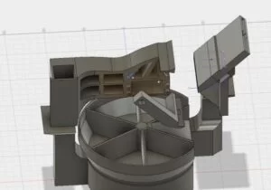
The hardware of this project serves the purpose of controlling the feed of resistors incrementally into the system, measuring the resistance, and placing the resistor into the appropriate bin. The user places mostly straight resistors into the feed slot, and the feed slot outputs one resistor at a time into the measurement arm via a mini solenoid that pushes one resistor from the stack over an edge. The measurement arm then rotates up and presses against the measurement surface to read a resistance value. Finally, the arm swings down to drop the resistor into the spinner before finally returning to the neutral position for resistor catching.
Design Philosophy
This project is designed to be printable, modular, and modifiable. In total, there are 8 independent pieces that fit together. The eight pieces and their purposes, approximate sizes, and images are shown below. All pieces are designed to slot together, and they are solidified with hot glue (other glues would suffice, but the rapid curing time of hot glue enables faster construction).
| Part | Description | Approximate Size (L x W x H mm) |
|---|---|---|
| 1 | Base | 270 x 154 x 140 |
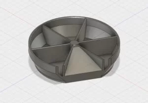
| 2 | Spinner | 160 x 160 x 38.5 |
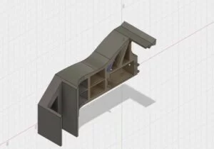
| 3 | Measurement Servo Holder | 148 x 56 x 96 |
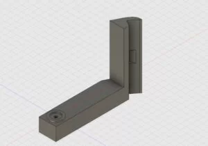
| 4 | Measurement Arm | 75 x 15 x 56 |
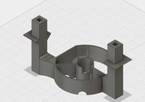
| 5 | Feed Mount | 40.4 x 78.8 x 100 |
| 6 | Feed Slide – In | 57.7 x 11.5 x 69 |
| 7 | Feed Slide – Out | 22.3 x 11.5 x 69 |
| 8 | Feed Plunger | 5.1 x 2.75 x 63 |
Hardware Components
- Base: The base is designed to hold the other components. It has mostly empty space to hold control circuitry and the PIC32 if moved off the Mircostick. The pegs on the center hold the stepper motor in place for spinner operation, and the measurement and feed mechanisms attach to the vertical posts.
Spinner: The spinner is designed to be large enough for straight resistors to fit easily. The bottom has a 10-pointed star shape engraved in it to attached to the stepper motor. The storage is split into 6 sections with one of them being a slot to return the resistor to the user immediately after measurement.
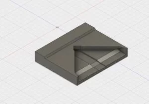
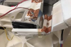
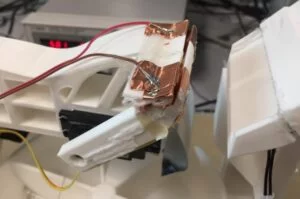
Measurement Servo Holder: This arm is designed to extend off from one post and house the servo to control the measurement arm. Metal electrodes are attached to two edges of the measurement edge to facilitate measurement. The servo hole is matched to the S3003 servo. The empty spaces in the arm are designed to minimize material used in the print.
Measurement Arm: The small arm screws into the servo and is the primary movement tool for the resistor post-feed. The arm is slanted so that the resistor stays in the groove when horizontal and upright for measuring, but slides out when lowered to drop the resistor. The center divot prevents the resistor from sliding around and allows the bulb of the resistor to not interfere with the measurement via the wire leads.
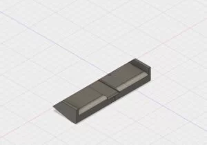
Feed Mount: The feed mount attaches to the other post and provides a place for feed solenoid and mount the other feed parts. The two parts of the feed slide are glued to this piece along with the mini solenoid.
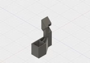
Feed Slide – In: This part holds the resistors to be sorted. The grove in the center guides the resistors through the feed mechanism, and the thin gap makes it so only one resistor can go through the mechanism at a time. The cut opening in the top allows the user to straighten out resistors that are tangled.
Feed Slide – Out: The output section of the slide guides the resistors after the plunger into the measurement arm. The open top of this piece prevents jamming and allows view of the mechanism working for checking functionality.
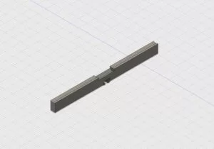
Feed Plunger: The plunger fits in between the input and output feed slide. When the solenoid is not powered, the plunger is flush with the input slide. One resistor can fit on the plunger at a time, and when the solenoid is activated it extends to allow the resistor to roll down the output slide.
Hardware Construction
The hardware for this project was designed in Autodesk Fusion 360 with intentions to be 3D printed on a Makerbot 2.0. The Makerbot imposes limits on size of the objects to print. Using a larger design and printer could allow easier operation. Included in the appendices are the STLs for printing, please contact Nathan Lambert at [email protected] if you desire the raw CAD files.
Electrical Component Design
In order to provide an interface between the mechanical design, the user, and the PIC32 software, 6 major electrical parts were used:
-
- Futaba S3003 Servo motor – We chose to use a servo motor to operate the arm that raised and lowered the resistor from the feed mechanism to the measurement contacts. Since the PIC32 can produce a PWM control signal via its output compare channel that is sufficient to control a servo, and the limited range of motion is not an issue since only moving between the contacts and the bins is needed, the servo was a logical choice.
-
- PF35T-48L4 Stepper motor – We needed a motor to rotate the bins underneath the measurement arm. We chose a stepper motor since this motor could easily be rotated continuously, but also in discrete angular steps so that we could control which bin the arm was over at any point in time without any additional feedback or sensor required. In addition to being easy to operate for this application, we were able to scavenge a suitable motor from the lab bins at no cost to us.
In order to operate the stepper, we used a spawned protothread to send pulses of 100 ms through to the ULN2003A driver chip as seen in Appendix C. The chip contained transistor arrays with flyback diodes which would supply up to 0.5A of current from the 5V supply to the motor when turned on. Through testing, we found that the time constant of the motor was such that, with the load of the bins connected to it, we could not operate significantly faster than 100ms between steps, else the motor would not complete the rotation in the time period and simply jitter in place.
- PF35T-48L4 Stepper motor – We needed a motor to rotate the bins underneath the measurement arm. We chose a stepper motor since this motor could easily be rotated continuously, but also in discrete angular steps so that we could control which bin the arm was over at any point in time without any additional feedback or sensor required. In addition to being easy to operate for this application, we were able to scavenge a suitable motor from the lab bins at no cost to us.
-
- Adafruit Mini Solenoid – We used the solenoid to actuate the feed mechanism to drop a resistor out of the hopper. Testing indicated that using the solenoid at its full rated 5V caused too strong a response, with resistors often flying out of the feed mechanism. In addition, the solenoid would tend to heat up, since it drew significant current. We added a power resistor in series to reduce the operating voltage of the solenoid to under 2V, which improved performance and reduced power consumption. The Control circuit schematic is part of Appendix C, and consists of a power NMOSFET for turning on the solenoid at the command of the PIC32, and a flyback diode to handle inductive spikes when the solenoid is turned off.
-
- Electrical Contacts – We created electrical contacts for the resistor out of conductive copper tape soldered to wire. We placed wire connections on both the top and bottom of the contacts to improve the connection which could be different based on irregularities in the resistor.
-
- 10 turn potentiometer – We used a 10 turn potentiometer to select menu items and set bin limits. The wiper was connected to a PIC32 input pin to be read by the ADC.
- Push Button Switch – A simple push button was used to select menu items. This was connected with a 10k Ohm pull down resistor to ground and to the PIC32. The debouncing was handled in software.
Software Design
Overview of Software & State Machine
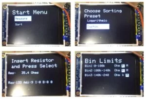
The menu navigation is handled by a state machine that guides the user through operational decisions to allow simple navigation to the user’s end goal. Each screen has a char value corresponding to its purpose; these are stored in vectors that contain all possible options for the state variable given a certain starting state. Start Menu and Sort Menu each have these vectors, with a few char values which each represent a potential next state. When navigating the menus, the user is changing the index value within these indices. Selection simply loads this value into the state variable, pushing the machine into the next state. The control thread determines which state is shown and translates inputs into variable values. The display thread reads the state and index variables and adjusts the display accordingly every ⅕ of a second to minimize flicker.
With respect to sorting, the menus serve to define bin limits for the sorting operation. Once defined, the menus also tell the system when to jump into the sorting procedure. The machine cyclically releases one resistor into the measuring arm, brings the resistor to the measurement leads, measures and prints the resistance of the resistor, and rotates the bins so the correct bin is aligned to the measuring arm. Finally, the arm releases the resistor into the correctly aligned bin. Figure 2 in the introduction shows the general progression of steps in the software.
The arm is controlled with a simple servo which we control by setting the duty cycle of the PIC32 output compare PWM channel. The rotating bins are controlled with a stepper motor, simply by turning on and off the appropriate channels at 100mSec increments. The rotation code is placed in a separate spawned protothread instead of a function since it requires the use of yield times. The resistor release is controlled with a solenoid that pushes a plastic stopper when driven with a high enough threshold voltage. These mechanical devices were all calibrated in timing timed through the PIC32 to create the correctly timed action described above.
The measurement autoranging feature and the CTMU is controlled by the PIC software. We first initialize the CTMU by modifying CTMUCONbits to turn on the CTMU module, disable the discharging, and enable the charging of the circuit. We initially start off with current level 1, the lowest possible current output by the CTMU. If the ADC reading is greater than 99 (~0.32 V) then we break out of the loop and use this value of current to calculate the resistance. Otherwise, the loop iterates through increasing current levels until an ADC value of 99 or the maximum current is reached. Therefore, we keep the current safely low and gradually step it up only when we know the next step will not exceed the tolerable voltage.
GUI Design
The GUI is designed to convey the required information as simply and efficiently as possible. The real estate available on the TFT screen is very limited, restricting the design to simple text. For selection, the most area-efficient option is a selection bar inverting the color of the text. This approach required no margin, saving area. This design was kept uniform for every screen for simplicity and consistency in the design.
After the design for the individual screens, the GUI was planned out to use as few screens as possible with clear options that facilitate easily navigated menus. Our sorter has a limited number of functionalities, so the menu system can be very simple. The pathing to each functionality is clear from the start, so the user should not need to search around the menus.
Usability
A concern throughout the design process has been usability; the user’s experience should feel straightforward and intuitive, while enabling the full range of functionalities designed into the project. The inputs should be as few as possible to simplify how the user interacts with our system, within reason. To these ends, the control system was designed to easily navigate the user to their desired functionality.
One considered input for the controller was a back button to reverse through the menu screens. In keeping the controller simple, we determined there are few enough menu screens that a back button is unnecessary. Reset fulfills this functionality in returning to the initial screen, meaning the back button would only be useful in returning to the sorting method screen from the custom select screen. This functionality is already available through a reset followed by choosing “sort” (the initial option) which is two button presses. The ease of this process and the limited use options for the back button helped us determine its implementation was unnecessary. Doubling the number of additional buttons (considering the reset button comes attached by default) was not justifiable considering the limited use the back button would have.
The final design for the control system is therefore a hand-held controller wired into the main device with two buttons and a dial. The controller is hand held to allow the user to read the screen at any comfortable position. In future iterations, designed with form in mind, the controller should have a designated place to rest on the sorting machine.
The first button is the hard-wired reset button, enabling the user to easily restart the machine. This button is out of the way, because when the user needs it, they are not concerned with anything else on the controller. The reset button is also out of the way to prevent accidentally pressing it while handling the controller.
Next is the selection button and analog wheel. The functionality of the device is selected through 2 menu screens the user navigates with these tools. The wheel is used to move a selection bar up and down the screen. The button is used to progress to the stage selected on screen. The menu navigation is relatively simple, since the device has few operation modes. Figure 13 below shows the menu screens and navigation options in the system.
The analog potentiometer is used over, say, selection arrows (up and down) because the dial is eventually used to input value ranges for the resistor. This functionality with buttons would be arduous. The analog wheel, which can serve both required needs, is therefore implemented.
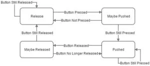
We must create a simple state machine to debounce button presses so users’ presses do not cause the system to jump ahead. The debounced button is a simple debouncer state machine, which double checks each button press and release to ensure they are not simply the product of noise. The state machine is implemented in the debounce() helper function as described below in Figure 14.
Results
Execution Time
At the moment, the execution speed of our resistor sorter is, on average, 10 seconds. The sorting stage can vary in execution speed since it depends on the number of bins that must be rotated through to get to the appropriate bin. For prototype development, we have a 5 second delay before each resistor feed for ease of mechanical debugging. In a production design, this could be reduced to 1 second, yielding a potential average execution speed of 6 seconds per resistor. This is significantly faster than a human can read a resistor with a multimeter and bin it appropriately. The table in the next section gives detailed time breakdown by step.
Mechanical Execution
This project was inherently limited by its mechanical accuracy. The accuracy of each moving mechanism contributes to the whole, and characterizing each individual part provides the most precise feedback for how to improve the system. For analysis, the three mechanical functions are the same as explained in high level design:
- Feed (70 ± 15% accuracy): The feed mechanism was the largest source of error. This is due to the inherently difficult shape that is a resistor. When feeding, it is imperative for orientation to remain as intended, or else there will be difficulty in later stages. This is a contrast to many sorting and feed mechanisms encountered in regular life where the feed mechanism takes advantage of the flexibility of the shapes being entered, such as round candies or coins. The failure modes for the feed mechanism predominantly are jamming issues and uncontrolled expulsions.
Jamming issues occur because of the precise movement needed for the mini solenoid in the feed and the manufacturing error of low cost 3D printing. The feed plunger arm either would not move if the package was compact or the system has cracks where resistor leads get caught when leaving enough room for motion. Optimizing between these two by regluing and shaving pieces down gave us our best results. Sometimes when a resistor jams, waiting a cycle will allow the solenoid to activate again and the resistor can properly exit the second time.
Uncontrolled resistor expulsions occur because of the fast activation of the solenoid. Even when reducing the power delivered to the solenoid, the actuation speed and power is high enough to induce more motion than needed in our device. This causes resistors to fly out of the track and past the resistor measurement arm. Once the resistor is not in place, there is no chance of measuring it and the system needs to be reset.
- Measurement (85 ± 7.5% accuracy): Physical resistor measurement was the next major source of error, but the errors were simpler as the moving parts in this stage need less precision. The measurement arm is designed precisely for ¼ watt resistors, which minimizes random error as long as the inputs follow that recommendation. The sources of error are mis-measuring the resistor by not making a solid contact to the measurement platform and lodging the resistor into the arm so it cannot be dropped.
Mis-measurement occurs when resistor does not rest well on the copper arm contacts, so the resistor measurement circuit sees open circuit and places the resistor into the largest bin. This error occurs to the precise nature of our design. Even when a resistor is added by hand, there is a chance that the thing metal resistor leads do not line up properly.
Permanently lodged resistors occur when the alignment of the resistor arm is too precise and resistors become lodged in the slot of the arm as it is pressed into the measurement apparatus. The soft nature of the copper measurement tape causes the copper to form to resistor leads, and over time the arm becomes more precisely shaped. This wire shaped indention grabs lightly onto the resistors through the entire range of motion of the measurement arm.
- Sorting (99 ± 1% accuracy): Sorting occurs after the measurement, and is a relatively minor source of error due to the precision of stepper motors. The only error is when the slots of the bins are misaligned.
Bin mis-alignment is primarily human induced error. When starting the system, the user needs to make sure the current bin number reading on the TFT display agrees with the bin positions. One misaligned, the bins do not automatically correct, so errors will persist. If aligned properly at the beginning, no new errors in alignment come about.
Accuracy & Calibration
In order to ensure that our resistor sorter would accurately measure the resistors it was presented with, we needed to calibrate the reference current source of the Charge Time Measurement Unit (CTMU) of the PIC32. While this component is given nominal specified current outputs, it does not have tolerance ranges on its specified output. We initially used the specified current and the measured voltage from the Analog to Digital Conversion Unit (ADC) to calculate the resistance with Ohm’s Law. However, we found that the results from this calculation were not sufficiently accurate. Through extensive testing, we identified five variables that affected the accuracy of the resistance measurement:
- ADC Autosampling: Using the ADC in autosampling mode significantly reduced the range of resistors we could measure. With autosample on, an open circuit would read around 100k Ohms. Turning off the Autosample greatly improved the range of resistors we could measure into the Megaohm range.
- ADC Sampling & Clock Speed: Running the ADC at high speeds caused unusual nonlinear voltage and current relations. When sampling at high speed, the charge/discharge time of the internal capacitor in the ADC can become longer than the sampling rate with high resistances attached. We solved the issues caused by this change by increasing the sample rate to the lowest speed possible (ADC_SAMPLE_TIME_31) and adding the largest possible clock divider (32) to decrease the ADC’s Clock rate (ADC_CONV_CLK_32Tcy).
- Wait Time between Setting Current and Sampling ADC: We realized that our Resistance Measurement code would give seemingly random answers if no time was given between changing the current source setting and sampling the ADC. It appears that making the change to the current source to output at a new level takes more time than a CPU instruction. We added 100 mSec of yield time to allow the new current level to settle before reading.
- Chip Manufacturing Variations in the CTMU Current Source: There are no accuracy specifications on the CTMU current source, and in our testing we found that in some instances our chip provided currents that were over 10 percent from nominal. In addition, the CTMU has a series resistance that is also poorly specified to the pin. We overcame this by using linear regression as described below to calibrate our measurement system.
- Intrinsic resistance of the current source when measuring high resistances: When measuring resistances in excess of 1M Ohm, the intrinsic resistance of the current source (likely implemented through FETs) becomes significant relative to the measured resistances. In order to combat this problem, we used a 3rd order polynomial regression model over our calibration set in order to model the nonlinear behavior of the system.
As discussed above, a number of accuracy concerns dictated that we calibrate our system. In order to calibrate, we used 31 known resistor values between 56 Ohms and 5.6M Ohms. Since the current source has 4 different potential values, (0, 3, 2, 1, from largest current to smallest), we tested and calibrated each current source separately with resistors that would fall into that current level during operation. Figure 17 shows the calibration data along with the fitted curves and equations implemented in the software.

As shown in the plots, the calibration curves lined up nicely with the calibration data points. The R squared value for each curve fit is 0.999 or greater, indicating that the models capture the vast majority of the variation in the data. The Largest raw error for resistors under 180 Ohms was 21.3 Ohms, and the largest percent error for resistors over 180 Ohms was 5.2%. For Resistors over 1500 Ohms, the largest percent error was 3.0%. Since most of the resistors used in labs have a 5% tolerance, and there is limited accuracy at low resistances, we desired to have errors in our measurement device of under 10% or 25 Ohms, whichever was greater. Thus the accuracies we have achieved are as desired as better.
Conclusions
Results vs. Expectations
Our project performs the function it was designed for – sorting resistors automatically – but it falls short of our desired performance targets by being rough at the edges. The core functionality of user interaction and resistor measurement and placement are reliable, but the feed mechanism that elevates the project’s autonomous ability to become viable and valuable to many labs requires additional iteration. The user interface and electrical control systems of the lab are polished and meet our goals, but the system can only be as good as the mechanical aspect as it is the weakest link and greatest challenge.
Next time, we would implement more iterations of physical prototypes to figure out what worked and what did not. Increasing the number of versions provides increased insight into the strengths and weaknesses of subtle changes. What we did was make versions that are close to working well and try to make physical changes to it to get it to reach full performance. The ideal method would be to print a full set of parts with minor variations in order to test them all simultaneously and identify trends in changing certain dimensions. This is the fundamental benefit of 3D printing and rapid prototyping, so we should have taken full advantage of this benefit when we decided to go with 3D printing to provide more polished construction. Other features that we considered implementing, but were left out due to limited time included speech playback of resistor values, increased number of resistor sorting bins, full hardware concealment within base of sorter, and external power sourcing.
Failure Mode Analysis
This section proposes work that could be done to minimize our sources of error. It is our hope that this section will encourage others to continue and improve on our design.
Feed: Overall the feed mechanism can be improved by being moved closer to the measurement arm and more precisely integrating the moving parts. Designing a different feed mechanism to attach to the base in another option to consider.
- Jamming: This would be reduced by printing the parts on a more advanced printer. Basic heated filament printers do not perform well with overhangs, so the feed mechanism had to be printed as separate parts and assembled with glue. Printing in one part would have reduced variation and allowed for more precise integration of the solenoid. Additionally, creating a apparatus that would precisely enter the resistors into the feed mechanism and or straighten the leads would substantially improve performance.
- Uncontrolled Resistor Expulsions: To reduce the force of the solenoid, users should look into ways to add damping. Ideal, one would find a way to add a roughly linear amount of damping uniformly across the feed plunger. Adding damping on one side would cause rotational effects and more error. An idea for this damping would be a loose spring and rubber band that initially opposes the fast turn on of the solenoid.
Measurement: This mechanism can be improved by optimizing the measurement arm shape. The motor controller integration does not present itself as contributing the problem.
- Missed Measurement Contact: This problem could be solved by redesigning the resistor arm and contact. The resistor arm we used was primarily designed to catch resistors from the feed mechanism. As the feed mechanism is improved, the resistor arm will be more flexible. When the contact errors occur, generally the resistor bulb is off center on the measurement arm and contacts the measurement surface and acts as a spacer preventing the arm from closing onto the contacts. This could be prevented by making a larger cavity for the resistor bulbs and making more flexible arm contactors.
- Permanently Lodged Resistor: Lodged resistors would be an easier issue to solve. A simple solution is to replace the copper electrodes periodically and therefore the copper contacts would not have grooves engraved onto them. Alternatively, one can replace the copper with a harder metal.
Sorting: The sorting bins only errors come from alignment. The motor control execute as expected.
- Misaligned bins: This could be solved by adding an additional sensor to calibrate the bin position before each use. By Adding a sensor on one bin, the bins could rotate to the ‘home’ position each time the PIC32 is reset.
Failed and Incomplete Ideas
Software: Original software plans included speech playback of the resistor value when in measure mode. This would have been done with an SPI DAC with a similar setup as done in Lab 2 the DTMF generator with speech playback. This was eliminated as it was outside our core functionality.
Hardware: The hardware design was originally hoping to be far more compact and effective. We needed to expand our design from the first-generation compact design to take into account the length of straightened resistor leads. Expanding the design made the margins on the design bigger and added more variability into the functionality. Therein, moving parts across wider ranges of motions lowered the conversation rate and increased operation time.
In addition, we hoped that we could build a larger hopper for resistors, so that a large number could be inputted at once, instead of a small queue such as is in our current design. Due to mechanical problems with resistors getting stuck, and the difficulty involved in controlling additional rotary and vibratory motors to prevent this, this idea was replaced with the simpler solenoid actuated feed mechanism.
Safety Considerations
We have taken a number of safety precautions, including:
- We used a power resistor to reduce the pull in voltage of the solenoid so that the resistors would not shoot out of the hopper if stuck, thus avoiding potential harm from small parts flying.
- The stepper motor is sufficiently low power that it can be stopped with gentle force (i.e. touching the sorting wheel, therefore preventing jamming of fingers, etc. in the rotating parts.
- Electrical connections have been solidly made & open live wires have been covered whenever possible.
- The current source used to measure resistors is kept low enough at all times so as to not be harmful to humans, and is stepped up from lowest current first and only stepped up if the impedance presented is low. This minimizes heat up of resistors and hence potential for fire.
Standards
We believe our design conforms to the two relevant standards that we identified in the introduction, IEEE 118-1978 and ISO 9241. Our approach to resistor measurement is to pass a known current source through the unknown resistor, and measure the voltage to calculate the resistance, which is acceptable for low accuracy current measurements per Section 4.1.1 of IEEE 118-1978. In addition, the auto ranging behavior that gradually steps up the current ensures that no overcurrent heating of resistors occurs that could cause inaccuracies in measurement as cautioned by Section 2.7 of IEEE 118-1978.
While as described above we were unable to consult ISO 9241 directly, we believe that our user interface design conforms to basic usability standards for GUIs. The Text is high contrast for readability, and there are only two input devices, the potentiometer and the button. It is quite intuitive in our testing to understand the functions of these two devices in moving the menu selection and selecting the highlighted option. By highlighting the active option that is to be selected, it stands out more to the user and thus is intuitively the item that will be selected.
Intellectual Property Considerations
As we desired to have a novel project and design, we did not reuse any previous design or attempt to reverse engineer a design. While there are some patents in this field as described in the introduction, these patents have long since expired and do not fully apply to our design, which is different in mechanical design and electrically in the use of microcontroller based autoranging. The two patents mentioned earlier use different mechanisms to measure and sort the resistors, and lack the user interface and flexibility that our system presents. These differences from the older patents presents a possibility of patenting our design. At the minimum, publishing this design would be feasible and is the plan of action.
We reused some code from Bruce Land’s Charge Time Measurement Unit webpage [11], which has been freely released into the public domain. The Protothreads library was developed by Adam Dunkels and amended by Bruce Land, and is again in the Public Domain. The TFT display libraries were developed by Adafruit and Syed Tahmid Mahbub, and again were released in the public domain. All other work is our own.
While we are freely publishing this work on this course website for intellectual enlightenment, this work is the property of the Authors (Alex Parkhurst, Brian Gross, and Nathan Lambert) and shall not be used in whole or in part without the express permission and acknowledgement of the authors. There are potential opportunities for us to revise this implementation for potential implementation or publishing in the future.
Ethical Considerations
In executing this project, we have abided by the IEEE code of ethics. Of particular note, section 3 of the code of ethics states that we shall “be honest and realistic in stating claims or estimates based on available data.” To this end, we have discussed in the Results section above the level of functionality of our design fully, and indicated areas in which improvements would be necessary for a commercial implementation. In section 7, the code mentions that we “seek, accept, and offer honest criticism of technical work.” To this end, we have consistently discussed as a team ways to make our system better, and are providing full details of our implementation with hope that others provide input to improve the system in the future. In the spirit of sections 5, 6, and 10 of the code, we believe that this project has been an excellent opportunity for our development as engineers in improving our understanding of the underlying technology, as well as managing a team through a major design project. We believe this report is an honest representation of our work, and in executing this project we have taken precautions to state our performance realistically, ensure the safety of everyone involved, and treat others with respect while expanding the boundaries of our knowledge.
Additional Legal Considerations
Beyond the intellectual property considerations above, we do not believe there to be any additional legal considerations that we need to take into account. We do not have any radio transmissions or other components regulated by law.
- How does the sorter measure resistor values?
The PIC32 uses the CTMU current source to apply a known current, measures voltage via the ADC, and calculates resistance with autoranging to step current until a usable ADC reading is obtained. - Can the bin limits be customized?
Yes, the GUI allows users to input custom bin limits via the 10-turn potentiometer and select button. - What motors control the measurement arm and the bins?
The measurement arm is driven by a Futaba S3003 servo and the bins are rotated by a PF35T-48L4 stepper motor driven through a ULN2003A driver. - How are resistors fed into the measurement arm?
A hopper and a feed mechanism use an Adafruit mini solenoid and a 3D printed feed plunger and slides to release one resistor at a time into the measurement arm. - Does the system include autoranging for safe measurement?
Yes, the CTMU current source is autoranged from lowest to higher currents, stopping when ADC reading indicates a safe voltage level. - What are the main accuracy limitations?
Mechanical feed reliability (jamming and uncontrolled expulsions) is the largest limitation; measurement contact issues also contribute, while sorting accuracy is high due to stepper precision. - How fast does the sorter operate per resistor?
Currently about 10 seconds per resistor on average; potentially reducible to about 6 seconds with shorter delays. - How is the user interface navigated?
The TFT GUI is navigated with a 10-turn potentiometer to move a selection bar and a single select button to choose options; a reset button returns to the start. - What calibration was performed for measurements?
They calibrated the CTMU/ADC using 31 known resistors from 56 Ohms to 5.6M Ohms and used regression models per current level to correct nonlinear behavior. - What safety measures are included?
A power resistor reduces solenoid voltage to prevent flying parts, low-power stepper that can be stopped by touch, covered live wires, and safe low current autoranging for resistor testing.