Summary of DIY remote control based on PIC16F628
This project describes a versatile remote control system capable of managing up to 8 devices via radio or infrared signals. It features configurable outputs that can operate as momentary or latched, with programmable toggle functions. The system uses a PIC microcontroller allowing flexible configuration including unique addressing and Manchester-coded transmission suitable for inexpensive ASK radio modules or IR control. Variants include 4 or 8-channel versions, and compatibility with multiple PIC models is mentioned. Related projects expand functionality for learning remotes and advanced digital outputs.
Parts used in the DIY remote control based on PIC16F628 Project:
- PIC microcontroller (PIC16F628, PIC16F630, or PIC16F676)
- ASK radio modules or Infrared LED and receiver components
- Push buttons (S1-S8 for transmitter channels)
- Diodes (D1-D4 for address setup, optional)
- Jumpers (J1-J4 for address setup, optional)
- Power supply (2-5.5 VDC for PIC MCU)
Control up to 8 devices by this easy constructable remote control. It can work as a radio or infrared remote control, depending on the components. Each device output can be configured to be momentary (turned on while you press the button) or latched. Latched outputs can be toggled on/off by one button per channel, or turned on and off by two buttons per channel.
Try it now, before building! Click on the transmitter buttons with the green labels on the left and see how the receiver outputs (K1-K8) change. Change the number of transmitter or receiver channels. Switch the receiver output type between latched and momentary.
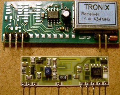
Containing a PIC microcontroller, the circuit is very flexible. You can decide which receiver outputs are latched and which are momentary. The Manchester-coded transmitter output is well suited for the cheapest ASK radio modules or for infrared control. The units are configurable to a unique address, which must match to control the devices.
Related project: Learning remote control receiver
Take your existing remote control and control everything with it. This receiver can learn codes from an RC-5 format IR remote control, and associate the buttons to different channels and actions.
Related project: 2^16 remote control encoder and decoder
If you have TTL signals to control remote digital output lines, please check this project instead.
If you have trouble with programming PIC microcontrollers, you can consider builing other circuits based on Holtek HT-12D, HT-12E, Princeton PT2262, PT2272 and Motorola MC145026, MC145027, MC145028 encoders/decoders.
4/8-channel V4.2 radio transmitter
The difference between the 4-channel and the 8-channel version is only the software inside. The 8-channel transmitter has one button (S1-S8) per channel. The 4-channel transmitter uses S1-S4 buttons to turn on, S5-S8 buttons to turn off channel 1-4 (use with latched outputs on the receiver). The D1-D4 diodes and J1-J4 jumpers are optional, and are used to setup the transmitter address. Higher supply voltage results higher transmit power, but V+ range is 2-5.5VDC for the PIC MCU. When V+ is higher than 5VDC, use separate power for the mcu.
Configure & download
What if you can’t get a pic16f630?
- use a pic16f676
- try a pic16f628, here is the modified transmitter
For more detail: DIY remote control based on PIC16F628

