Summary of Aurora 9×18 RGB LED art
This article details the construction of Aurora 9x18, a circular LED art piece with 162 RGB LEDs controlled by a PIC24F08KA101 microcontroller. The project utilizes a hybrid PWM and multiplexing technique to achieve high-resolution color control using only one PWM module. It covers circuit design, PCB fabrication, parts sourcing, and SMD assembly methods required for this complex build.
Parts used in the Aurora 9x18:
- 162x 5mm Tricolor LED (common-cathode)
- 1x PIC24F08KA101 Microcontroller
- 3x DMP3098L MOSFETs
- 12x MMBT2222A BJTs
- 1x AP7333-33 or AP7313-33 Voltage Regulator
- 1x 4-way Stick Switch (Panasonic EVQQ7)
- Resistors (150 Ohm, 220 Ohm, 1k Ohm, 470 Ohm, 10k Ohm)
- Capacitors (10uF, 1uF)
- 5V regulated power supply or 4 NiMH batteries
*** Check out my blog for updated version of this project and more! ***
My obsession of LEDs has led me to this. Aurora 9×18 is a thing of beauty (if I can say so myself) – has 162 RGB-LEDs in a circular configuration. The color of each circle is controlled by a microcontroller using a twisted form of PWM.
The microcontroller (PIC24F08KA101) only has one PWM module, yet Aurora is capable of 27 (9xR,G,B) independent brightness control. This Instructable reveals the inner-working of Aurora 9×18 through the building process.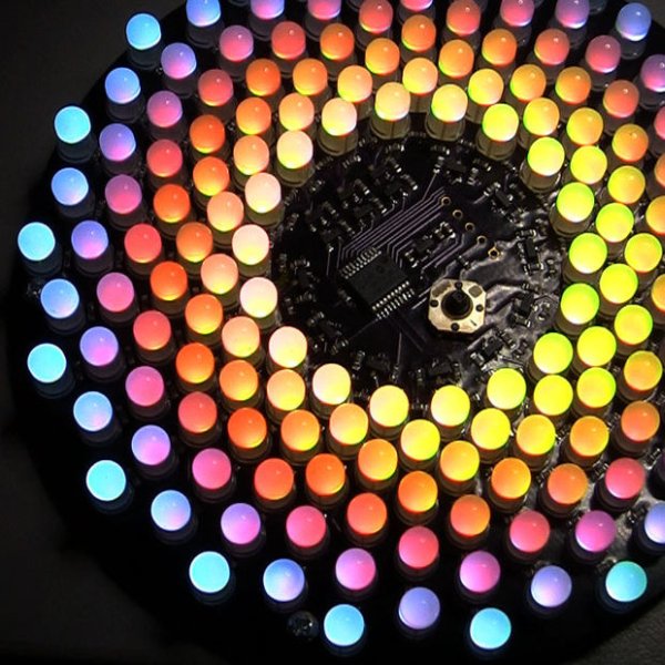
Step 1: Concept
A RGB LED is nothing more than a LED that actually encases 3 small LEDs of primary colors inside. RGB LEDs can create wide range of colors by combining 3 primary colors – Red, Green, and Blue. By changing the ratio between the 3 colors, you get many in-between colors. RGB LEDs are often called full-color LEDs.
Most of brightness controlling circuit utilizes the method called PWM. Many of microcontrollers today have a PWM controller or more built in, however there are usually less than 4 or 5 of them in a controller. So if I were to control 9 LEDs, I needed to use multiple controllers or external circuits. If those 9 LEDs were RGB LEDs, then there would be 27 PWM controllers needed.
I’ve gone through a few approaches – multiple microcontrollers working together in various configurations – some are complex and exotic. I was trying to solve more than just the number of LEDs that I can control – I wanted to make the fades in/out of brightness as smooth as possible. Turned out, 8 to 10 bit PWM resolution that most PIC microcontrollers provide was not good enough to create smooth transition in the darker/dimmer part of the brightness change. When the brightness is low, the transitions look more like steps than fading. Due to human eye’s non-linear or exponential response to light intensity necessitates gamma correction of the brightness change curve, which requires at least 12 bits of PWM resolution to give smooth fades (in my conclusion).
If I simply design a circuit where each LED is controlled by it’s own PWM controller having 12 bit or more resolution, I’d have to use a speciality LED controller IC. While this solves the problem, the added cost and size to the final product did not appeal to me. (Those LED controller IC are not very small or cheap.)
So I came up with an idea of combining PWM with multiplex drive. I further broke up each PWM cycle into multiple pulses, so that multiple LEDs were lit multiple times within one PWM cycle. (Kind of hybrid between PWM and PDM, I guess.) This way, the average output of LEDs are the sum of the many pulses within the short period. By combining more than one PWM pulses increases effective PWM resolution.
This technique also helpes reduce the perceived flicker of the light out of LEDs. Aurora 9×18’s LED refresh rate is about 246 Hz, but LEDs blink a lot more often. This creates the illusion of much higher refresh rate.
Take a look at the timing chart. I picked 7 LEDs and R/G/B bus signals to present the concept.
As you can see, R/G/B buses go up momentarily, taking turns. These pulses control the actual duration that LEDs light up. Each common lead of the LEDs controls whether that LED will light during the period that R/G/B buses go high. The actual timing that LEDs light up are marked with the color on the chart.
The condition here is:
LED 1 is on level 1 red (the lowest brightness).
LED 2 is on level 2 green.
LED 3 is on level 3 blue.
LED 4 is on level 3 yellow (red + green).
LED 5 is on level 3 purple (red + blue).
LED 6 is on level 3 turquoise (green + blue).
LED 7 is on level 255 (maximum brightness) white.
* time scale is about 8.1 ms for the entire width of the chart.
Hope this explains the way Aurora controls the brightness/colors of LEDs.
References
– PWM on wiki
– PDM on wiki
Correction
LED refresh rate originally stated was wrong – it’s 246 Hz not 123 Hz.
Step 2: Circuit
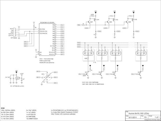
Aurora 9×18 has 18 RGB-LEDs in each of 9 circles, total of 162 LEDs. Each circle is LEDs are connected in parallel, so there are 9 LED circuits (x3 because they are RGB) to control.
I chose PIC24F08KA101 as the controller. It needed to be powerful enough (16 bit), and requires minimum of external parts (no crystal needed to run at the max speed of 32 MHz) to save space.
The circuit itself is quite simple. The microcontroller is connected to a joystick like switch (5 switches in it) and there are 3 MOSFETs and 12 BJTs controlling the current that goes into LEDs. There’s a 3.3V linear voltage regulator to supply for the PIC as well. (The LED circuit is driven by 5V power.)
If you look at this circuit you might realize that it’s just like 9×3 matrix circuit, but instead 3 rows are replaced with 3 primary colors of RGB LEDs. So now you know that RGB channels are multiplexed – in other words those 3 colors turn on one by one, not together at the same time. In general I don’t like multiplexing, but I needed to compromise in favor for the simplicity and physical space.
Given that this microcontroller only has one PWM module (to control the brightness of LEDs), I had to come up with a way of extending that PWM signal into 3. I’m doing that with a simple “AND” logic utilizing the lower part of the R/G/B bus driving circuit. In short, R-BUS only turns on when PWM signal is high and R-DRV signal is low. For G-BUS, PWM -> high and G-DRV -> low, and so on. This circuit works remarkably well, saving my precious space on the board and a few dimes.
I’m using MOSFET on the high-side switch simply because BJTs that I can find in the small package do not handle the current drawn by 162 LEDs in parallel (about 3 A peak!). This MOSFET (DMP3098L) has a remarkable current handling capability. Highly recommended.
Low-side (column, or each LED) driver/switch circuit is very straight forward. NPN BJT in common emitter configuration.
There are 1k Ohm resistors connected to the output of each driver, which some of you wonder as to why. Those resistors help the transistors turn off quicker when there are no LEDs conducting (transistors turn off quicker when there is current going through drain or collector). Those transistors are switching at the timing in the order of nanoseconds, so turn on/off speed becomes critical.
In a nutshell, those resistors allow PWM to run at a higher speed (less visible flicker).
References
– PIC24F08KA101 datasheet
– DMP3098L datasheet
Step 3: PCB
I wanted to make this object as small as possible, so designing the PCB took some work. In reality, I went back & forth between the circuit design and PCB design, trying to reduce part count to the minimum.
I had the PCB fabricated by DorkbotPDX. They have a community based PCB program (kind of like BatchPCB) that I like. As you can see, the boards are beautifully manufactured (in the USA :). The solder mask is dark purple.
Links
– DorkbotPDX PCB Order
Step 4: Parts
Here are the list of parts, or BOM. You can download BOM file that can be uploaded to Digi-Key for quick ordering.
162x 150Ohm (0603)
9x 220 Ohm (0603)
13x 1k Ohm (0603)
3x 470 Ohm (0603)
1x 10k Ohm (0603)
2x 10uF (0603)
1x 1uF (0603)
1x AP7333-33 or AP7313-33
3x DMP3098L
12x MMBT2222A
1x PIC24F08KA101
1x 4-way Stick Switch (Panasonic EVQQ7)
162x 5mm Tricolor LED (common-cathode) – AliExpress.com
1x 5V regulated power supply or 4 NiMH batteries & case
I source LEDs directly from China via AliExpress . Takes a few days for delivery, but the prices are great. Other parts are available at Digi-Key .
You can substitute transistors if you have something compatible. BJTs can be substituted by number of others, finding substitutes for the MOSFET might not be easy, however. Please let me know if anyone knows of a more economical devices here.
Step 5: Tools & Supply
- Magnifier visor or other visual aid device
- Solder paste in syringe
- Tweezers
- Electric hot plate
- Soldering iron
- Solder (flux core. go for the highest quality solder you can afford.)
- Wire cutter (I recommend this one.)

- Microchip PIC programmer (supports PIC24F08KA and capable of In-circuit programming through a standard 6-pin ICSP connector) and a computer
Step 6: Assembly
Due to the high number of part count (371 parts), and tight and unusual placements. The assembly requires excellent soldering skills and takes quite an effort.
As most of the parts are SMD (surface mount device), I use “paste, place & grill” method. If you have built a few things with SMD, you would know what I mean. There are many ways to solder SMD parts, and you are free to go with any method that you are comfortable with. I will show how I’ve done this one.
1. Count and prepare all SMD parts for the placement
I recommend prepping the SMD parts, so that they are ready to be placed on the PCB as soon as you dispensed the solder paste on it.
Step 7: Assembly 2 – Dispense solder paste on PCB
I wanted to use stencil for this step, but unfortunately due to the PCB layout I could not have made the stencil (low cost stencils can not contain non 90 degree angle parts). So I manually dispense microscopic dubs of solder paste using a syringe. This is a tortuous process.
For more detail: Aurora 9×18 RGB LED art
- How does the microcontroller control multiple LEDs with only one PWM module?
The author combines PWM with multiplex drive, breaking each cycle into multiple pulses so that multiple LEDs light up sequentially within one period. - Why was 12-bit PWM resolution chosen over standard 8 to 10-bit options?
Standard resolution creates step-like transitions at low brightness due to human eye non-linearity, whereas 12 bits allows for smooth fades requiring gamma correction. - What is the actual LED refresh rate of the Aurora 9x18 project?
The corrected LED refresh rate is 246 Hz, which creates an illusion of a much higher rate to reduce perceived flicker. - Which MOSFET model is recommended for the high-side switch in this circuit?
The DMP3098L is recommended because it handles the peak current of about 3 A drawn by the 162 parallel LEDs. - What is the purpose of the 1k Ohm resistors connected to the driver outputs?
These resistors help transistors turn off quicker by allowing current to flow through the drain or collector, enabling faster switching speeds. - Can the BJTs be substituted with other components in this project?
Yes, BJTs can be substituted by finding compatible numbers, though finding substitutes for the specific MOSFET might not be easy. - What assembly method was used for the surface mount devices?
The author used a paste, place, and grill method involving manually dispensing solder paste with a syringe since a stencil could not be made. - Where were the LEDs sourced for this project?
The LEDs were sourced directly from China via AliExpress to take advantage of great prices despite delivery times.