Abstract:
We have developed a mechatronic system to solve the famous Tower of Hanoi problem as part of a Carnegie Mellon University class. This class seeks solutions which solve the problem in under three minutes for the four disk case, using only the number of disks, source peg, and destination peg as user inputs. Our solution utilizes a spinning base to align pegs with a gripping unit. Raising and lowering the gripping unit is achieved through the use of a lead screw powered by a DC motor. The disk gripping is then completed with a novel two-piece clamping design, which uses six-point contact with each disk. Our system seeks to accomplish this task using only touch buttons as position feedback sensors. This button system, along with other design oddities, results in a unique approach to solving this problem. We will describe the design that we chose, the problems that we encountered, the way that we overcame them, and the obstacles which remain.
- System Overview
This year’s mechatronic design project was ‘Towers of Hanoi Solver.’ The towers of Hanoi puzzle was invented by the French mathematician Edouard Lucas in 1883. Given tower of disk, the objective is to transfer an entire tower of disk from one peg to another peg. Only one disk can be moved at a time and a larger disk can’t be on a smaller one. The objective of this design project is to design and build a mechatronic system (or robot) which solves the Tower of Hanoi puzzle autonomously. The system is only provided the starting peg, ending peg, and number of disks.
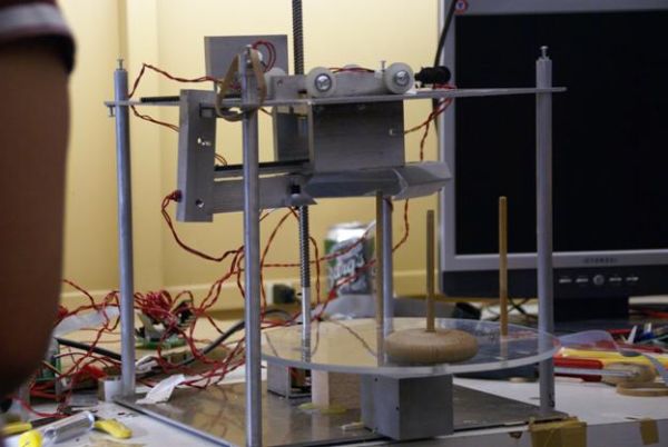
Figure 1.1 This shows the overall system
The system consists of 3 main components, as shown in figure 1.1. They are the turntable subsystem, elevator subsystem, and gripper subsystem. The gripper subsystem’s objective is to grab a disk and hold it in place. The elevator subsystem then raises and lowers the gripped disk to the desired height. Finally, the turntable subsystem rotates the gripper so that target peg can align with position of gripper. We used push buttons for the system’s sensors. All subsystems should coordinate together to complete the project objective.
1.1 Desired functionality
The goal of this project is to build the Tower of Hanoi solver while meeting the specifications. To achieve the goal, we require the following functionalities:
- Mechanical subsystem: it should be able to pick up and releases the disks. Then, it will move the disk to its destination peg. The mechanical subsystem should also be robust. Furthermore, the drive mechanism and motors should provide a sufficient amount of torque with a shortest amount of time.
- Sensor subsystem: it should be able to identify the type of the disks in the peg. Additionally, it should be able to measure the positions that our mechanisms.
- Software: it should be able to solve the Tower of Hanoi Furthermore, the user interface will be implemented in MATLAB to display the performance-related information. For the PIC microcontroller, it should be able to get the input from the GUI and control the sensor and the motors.
- Circuit: it should be built to input and output the correct voltages to and from the PIC. Besides that, it should be neat and clean.
- Power supply: it is needed to provide the right amount of current and voltage to the circuit.
With all of the above required functionalities, our system will be able to solve the Tower of Hanoi problem and implement it with precision.
- System
With the consideration of the goal and the desired functionalities, we have designed the following systems. Figure … shows the system block diagram.
Figure 2 System block diagram
2.1 Mechanical System
There are three main mechanical subsystems: turntable, gripper and elevator unit.
2.1.1 Turntable Subsystem
Turntable subsystem is where 3 pegs are located. Circular base will be rotated by a servo motor. Our prototype design had a DC motor with gearbox attached. Our original plan was using encoder to control the turntable. When we made our first turntable subsystem, we chose gear ratio of 1:6. The gear ratio didn’t reduce the speed enough, thus encoder couldn’t provide enough precision. The servo motor provided relatively easier control and simpler mechanism. It also provided enough precision.
The only disadvantage of having a servo motor as an actuator for the turntable subsystem was limited angle of operation. Operation range of the servo motor was little over 180 degrees. Bigger size of rotating base was needed due to limited angle of operation, since gripper subsystem should not hit any other pegs or discs.
Figure 2.1.2.1 Final Design of Gripper Subsystem
The main task of the gripper subsystem is grabbing disc in place. Our gripper design has a unique design. We have 6 kinds of discs to grab, and they all have different radius, height and curvature. We wanted our gripper design to be fully capable of grabbing all 6 different discs. Other goal of the gripper system was to avoid wobbling motion while the disc is at grabbed state. In order to do that, the gripper was required to have at least 3 points of contact, with each contact point being 120 degrees apart from each other.
Figure 2.1.2.3 Points of Contact
This is how our first design of the gripper looks like. It has 3 points of contacts between the gripper subsystem and a disc. A rectangular block on the right side of the picture is a clamp that opens and closes the gripper. Also there is an elongated hole on top of the triangular gripper piece. This elongated hole is a clearance hole for a peg to go through during operation of Hanoi tower solver. There is a reason that this hole is an elongated hole instead of being a circular hole. When target disc has a smaller radius than the one in the picture, position of the center hole of the target disc should shift to left with respect to the gripper subsystem’s position. To provide clearances for all discs which have different geometries, the clearance hole had to be elongated.
Figure 2.1.2.4 6 Points of Contact
The main difference between the final design and the prototype design is a presence of v-block feature. V-block features are located at interior walls of gripper and also at the clamp. V-block increased number of contact points. There are 6 points of contact in the final design, making grabbing more stable than the prototype design. There is another advantage of having v-blocks. When grabbing discs, the target disc will be centered automatically, no matter how big the disc is.
Figure 2.1.2.6 Gripper holding disk
The gripper subsystem has 2 degrees of freedom. Two JAMECO gear-head motors were used. These motors have integrated gearboxes with 1:50 gear ratio. Both motors use rack-and-pinion system to transmit motion. One motor actuates the clamp to open and close. The other motor actuates whole gripper system to slide horizontally. Horizontal motion of whole system is required because position of target peg depends on the size of target disc.
2.1.3 Elevator Subsystem
The elevator subsystem translates top plate vertically. Objective of the elevator subsystem is to move the gripper subsystem, which is attached to the top plate, to desired height. One JAMECO gear-head motor with gear ratio of 1:60 was used. A Lead screw was used for power transmission. Lead screw was chosen to prevent backlashes, since the lead screw is not back-drivable. This sub-system requires the most torque among 3 sub-systems because the top plate has to move with heavy gripper subsystem attached.
Figure 2.1.3.1 Elevator subsystem
2.2 Electrical System
The task for the electrical subsystem is to provide the interconnection between the mechanical subsystem and the software. Thus, the circuits are needed to be built such that it will provide correct voltages and currents to the motors and the PIC.
In the initial design, the sensors that we used are the encoders and the SHARP IR detector. The encoder would accurately measure the position that the turntable rotated, the height of the raising unit and the distance that the gripper moved. The use of encoder will allow us to have a feedback control, using PIC controllers. As a result, we can accurately pick up and release the disks. However, due to the integration problem, which we will elaborate in the result section, we decided to eliminate the use of encoders and changed the type of motor for the rotating unit. Additionally, to identify the types of disks in the starting peg, the SHARP detector was used. However, toward the end of the class, it got broken. Hence, this led to the decision of using only the buttons as our sensors. Therefore, the current circuit that we use consists of the PIC board and the motor board. Although the current circuit doesn’t have the encoder and the IR detector circuits, they will be presented for a completeness sake. As a result, in this section, we will illustrate the circuit in the PIC board, the motor driver circuit and the encoder circuit.
2.2.1 PIC board
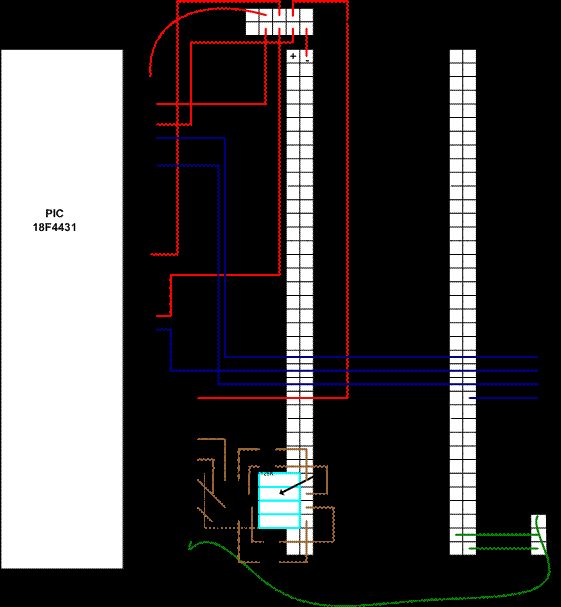
The PIC board consists of the PIC microcontroller, its circuit, and the button circuit. The PIC circuit consists of a crystal, capacitors, resistor, voltage regulator, and the dual drives/ receiver (MAX232). It also contains the connectors to other electrical subsystems such as the motor drive board and RC servomotor. The PIC outputs the voltages to the motors and inputs the voltages from the buttons, which is our sensor in this case. The circuit for the buttons are built on the PIC board. It consists of a SPST button and a 128K resistor. Its schematic is shown in figure 2.2.1.1. This board is powered by 12V from the power supply. The board layout is shown in figure 2.2.1.2.
For more detail: Towers of Hanoi Final report


