
Summary of LED dot matrix scrolling message – 14×5 – source code
This article details a scrolling message badge project using a PIC 16F884 microcontroller and two small 1.9mm LED matrix modules (14x5). The author replaces older chips with limited FLASH by utilizing the 16F884's 4K memory. A key innovation is mapping IO pins randomly via software tables rather than fixed connections, supporting both common anode and cathode modules. The system uses proportional fonts and precomputed bitmaps stored in RAM to generate scrolling text.
Parts used in LED dot matrix scrolling message:
- PIC 16F884 microcontroller
- Two 1.9mm ready-made LED matrix modules
- SMD adapter PCB
- EEPROM for storing messages
I have built various scrolling message badges for instance using the 16F57- 10×5 and 12×5. However, since these chips only have a small FLASH, there is not much flexibility. I don’t really recommend these controllers for a scrolling message.
Recently I have started a new project, using small 1.9mm ready made modules, and a 16F884. It has 4K FLASH which is sufficient (about 1/3 are used), and 256 bytes RAM. However, the max. continuous RAM is only 80 bytes.
edit: I am now using 2 RAM banks (160 bytes).
The font is proportional, most characters are 4 pixels wide, some are 3 only, and a few are 5 pixels wide. The complete bitmap is precomputed, which requires a large RAM buffer.
This time I tried something new- mapping all the IO randomly, and connecting the LED matrix to just any IO lines. For this purpose a number of tables are used. Also the TRIS registers are setup automatically.
It works so far, however, right now the text is not scrolling. However, this is only a minor additional effort. Also it turned out one module is common anode, the other common cathode, so two sets of tables are required. It is actually easy to correct the layout using these tables.
Table 1 is simply the order of the anodes and cathodes according to the datasheet.
The second table contains pointers to PORT variables, on correlation to the pin numbers in table 1, and in ascending order. The third table contains bit masks to set/reset individual bits (actually distributed over random ports). Also there is a table for the TRIS pointers for automatic setup.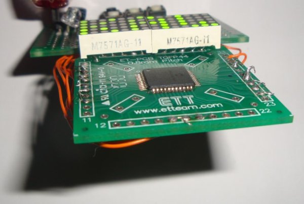
here you can see the SMD microcontroller, mounted on adapter PCB. The modules are simply soldered directly into the adapter board- this works, since random IO is possible via software.
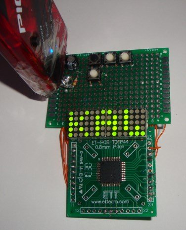
The LED matrix! It works correctly, the bitmap is copied from the display buffer. In order to scroll the complete bitmap, it is just neccessary to slide a window from the scroll bitmap.
The scroll is generated using the font table, and one of the preprogrammed texts from a table. Later, it is also planned to use keys to program a message directly into the chip, and store it into the EEPROM.
Here the source code, without the scrolling implemented (it is already partially programmed, and not much of an effort)
//
// LED matrix scrolling message
// 16F midrange PICs can use max. 80 bytes RAM area
// Extended midrange can use *more*
//
// Current configuration: PIC 16F884
//
// (c) by Takao 2014 – Hitechworld Software
// If you like this source code + use it,
// why not send some funds to [email protected] (with paypal)?
//
// All rights reserved, no ownership is transfered.
// You can use this source code for evalution.
//
#if defined(__XC)
#include <xc.h> /* XC8 General Include File */
#elif defined(HI_TECH_C)
#include <htc.h> /* HiTech General Include File */
#endif
#include <stdint.h> /* For uint8_t definition */
#include <stdbool.h> /* For true/false definition */
#include “system.h” /* System funct/params, like osc/peripheral config */
#include “user.h” /* User funct/params, such as InitApp */
#include “chrset.h”
#define c_phases 5
unsigned char v_main_phase,v_PORTA,v_PORTB,v_PORTC,v_PORTD,v_PORTE;
unsigned char i;
// pin configuration for the display
const unsigned char anodes[]={8,7,10,3,1};
const unsigned char cathodes[]={12,11,2,9,4,5,6};
const unsigned char cathodes2[]={7,9,4,1,2};
const unsigned char anodes2[]={12,11,10,3,8,5,6};
// IO pin assignment (above pins in ascending order
const unsigned char* const pin_port1[]={
&v_PORTC,&v_PORTC,&v_PORTC,&v_PORTC,\
&v_PORTD,&v_PORTD,&v_PORTD,&v_PORTD,\
&v_PORTD,&v_PORTD,&v_PORTB,&v_PORTB};
// TRIS registers for automatic configuration
const unsigned char* const tris_port1[]={
&TRISC,&TRISC,&TRISC,&TRISC,\
&TRISD,&TRISD,&TRISD,&TRISD,\
&TRISD,&TRISD,&TRISB,&TRISB};
const unsigned char* const pin_port2[]={
&v_PORTD,&v_PORTD,&v_PORTC,&v_PORTC,\
&v_PORTC,&v_PORTC,&v_PORTA,&v_PORTA,\
&v_PORTE,&v_PORTE,&v_PORTE,&v_PORTA};
const unsigned char* const tris_port2[]={
&TRISD,&TRISD,&TRISC,&TRISC,\
&TRISC,&TRISC,&TRISA,&TRISA,\
&TRISE,&TRISE,&TRISE,&TRISA};
// set or reset a bit
const unsigned char const pin_bit_set1[]={
0x80,0x40,0x20,0x10,0x08,0x04,\
0x10,0x20,0x40,0x80,0x01,0x02};
const unsigned char const pin_bit_reset1[]={
0x7f,0xbf,0xdf,0xef,0xf7,0xfb,\
0xef,0xdf,0xbf,0x7f,0xfe,0xfd};
const unsigned char pin_bit_set2[]={
0x02,0x01,0x08,0x04,0x02,0x01,\
0x40,0x80,0x04,0x02,0x01,0x20};
const unsigned char pin_bit_reset2[]={
0xfd,0xfe,0xf7,0xfb,0xfd,0xfe,\
0xbf,0x7f,0xfb,0xfd,0xfe,0xdf};
const unsigned char c_shl[]={1,2,4,8,16};
unsigned char v_sys_flags,v_led_ctr;
const unsigned char msg1[]={‘K’,’A’,’W’,’A’,’S’,’A’,’K’,’I’,’ ‘,0};
const unsigned char* const msg_arr[]={&msg1,&msg2};
#define display_buffer_size 14
unsigned char display_buffer[display_buffer_size];
unsigned char msg_buffer[80];
unsigned char msg_buf_idx;
unsigned char curr_msg_idx;
unsigned char curr_scroll_idx;
#define display_width 14
void configure_tris()
{unsigned char* tris_reg;
for(i=0;i < 12;i++)
{
tris_reg=tris_port1[i];
*tris_reg&=pin_bit_reset1[i];
tris_reg=tris_port2[i];
*tris_reg&=pin_bit_reset2[i];
}
}
unsigned char reloc_ascii(unsigned char c)
{
if(c > 64)return(c-65);
if(c > 47)return(c-22);
if(c==32)return(39);
if(c==45)return(37);
if(c==46)return(38);
if(c==0)return(0xff);
}
void generate_scroll()
{// build the scroll bitmap in RAM from the font data
unsigned char* curr_msg;
unsigned char* font_data;
unsigned char chr,font_data_size,font_data_value;
curr_msg=msg_arr[curr_msg_idx];
reloop:// load a character
chr=reloc_ascii(*curr_msg);
if(chr==0xff)goto rdy;
font_data=alpha_chr[chr]; // first character contains size bits
font_data_size=(*font_data) > > 5;
font_data_value=(*font_data)&0b11111;
for(i=0;i < font_data_size;i++)
{// copy bitmap data from font data to scroll bitmap
msg_buffer[msg_buf_idx]=font_data_value;
msg_buf_idx++;
font_data++;
font_data_value=*font_data;
}
msg_buffer[msg_buf_idx++]=0;
curr_msg++;
goto reloop;
rdy:;
}
void update_display_buffer()
{unsigned char src_start;
src_start=curr_scroll_idx;
for(i=0;i < display_width;i++)
{// scroll the message by incrementing curr_scroll_idx
display_buffer[i]=msg_buffer[src_start++];
if(src_start > msg_buf_idx)
{
src_start=0;
curr_scroll_idx=0;
}
}
}
//void clr_display_buffer()
//{
//for(i=0;i < display_buffer_size;i++)display_buffer[i]=0;
//}
void refresh_line(unsigned char v_phase)
{unsigned char anode,cathode,v_shl;
unsigned char* portio;
for(i=0;i<c_phases;i++)
{// activate one matrix line
anode=anodes[i]-1;
portio=pin_port1[anode];
if(i==v_phase)*portio|=pin_bit_set1[anode];
else *portio&=pin_bit_reset1[anode];
anode=cathodes2[i]-1;
portio=pin_port2[anode];
if(i==v_phase)*portio&=pin_bit_reset2[anode];
else *portio|=pin_bit_set2[anode];
}
v_shl=c_shl[v_phase];
for(i=0;i < (display_width/2);i++)
{// copy data from the display buffer
cathode=cathodes[i]-1;
portio=pin_port1[cathode];
if(display_buffer[i]&v_shl)*portio&=pin_bit_reset1[cathode];
else *portio|=pin_bit_set1[cathode];
// 2 display modules
cathode=anodes2[i]-1;
portio=pin_port2[cathode];
if(display_buffer[i+7]&v_shl)*portio|=pin_bit_set2[cathode];
else *portio&=pin_bit_reset2[cathode];
}
// update hardware ports
PORTA=v_PORTA;
PORTB=v_PORTB;
PORTC=v_PORTC;
PORTD=v_PORTD;
PORTE=v_PORTE;
}
/******************************************************************************/
/* Main Program */
/******************************************************************************/
 void main(void)
{
/* Configure the oscillator for the device */
//ConfigureOscillator();
/* Initialize I/O and Peripherals for application */
InitApp();
configure_tris();
curr_msg_idx=1;
curr_scroll_idx=0;
msg_buf_idx=0;
generate_scroll();
update_display_buffer();
v_sys_flags=0;
v_led_ctr=0;
v_main_phase=0;
while(1)
{
if(v_sys_flags&1)// timer interrupt was raised
{
v_sys_flags&=0xfe;
refresh_line(v_main_phase); // do multiplex refresh
v_main_phase++;if(v_main_phase==c_phases)v_main_phase=0;
v_led_ctr++;if(v_led_ctr==0x50)// blink the LED
{
v_led_ctr=0;
if(v_sys_flags&0x2)
{
v_sys_flags&=0xfd;
PORTBbits.RB6=1;
}else
{
v_sys_flags|=0x02;
PORTBbits.RB6=0;
}
}
}
}
}
For more detail: LED dot matrix scrolling message – 14×5 – source code
- Why was the PIC 16F884 chosen over previous controllers?
The 16F884 offers 4K FLASH which is sufficient for the project, unlike smaller chips like the 16F57 that lack flexibility. - How does the project handle random IO pin mapping?
The code uses several tables containing pointers to PORT variables, TRIS registers, and bit masks to automatically set up the hardware configuration. - What types of LED modules are connected to the board?
The project connects one common anode module and one common cathode module, requiring two sets of data tables. - How is the scrolling effect generated in the software?
A window slides across the complete bitmap in the scroll buffer, copying data from the font table and programmed texts into the display buffer. - Can users program messages directly into the chip?
Yes, it is planned to use keys to program a message directly into the chip and store it into the EEPROM. - What is the maximum continuous RAM usage mentioned for this configuration?
The original max continuous RAM was 80 bytes, but the author later switched to using 2 RAM banks totaling 160 bytes. - How are characters sized in the font implementation?
The font is proportional where most characters are 4 pixels wide, some are 3 pixels, and a few are 5 pixels wide.
