Step 1: Parts List
RC transmitter/receiver set with at least 3 channels. As is this code only works with stacked PWM signals. I can only say for sure that it will work with traxxas receivers. With modification it could work with any PWM timing, and I am working on making it work with synchronous PWM like the newer Futaba systems use, that is the pulses all begin at the same moment. It will not work with VEX rc systems, which use a different kind of signal.
since this is going to be in a SparkFun sponsored contest, links to the parts on that website are provided, conveniently these pages also have the datasheets
Electrical
2 9V rechargeable batteries, or any other array of of batteries that gives you 9 to 24 volts.
2x 9V battery connectors
A few feet of 22AWG or similar hook up wire (solid recommended if you don’t know which you prefer)
Electronic components:
1x perf board with 0.1″ spacing, about 2×3 inches in size
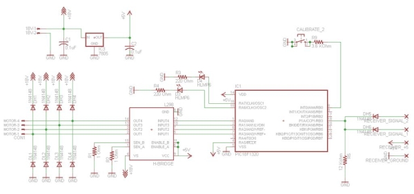
1x L298 Dual bridge driver
1x PIC18F1320
2x 0.1uF ceramic capacitors for regulator. (the code of 0.1uF is “104”)
1x 18 pin IC socket (recommended but not strictly needed)
1x 5V regulator
2x small 3mm LEDs for indicators. (use a green and a red instead of two reds like i did.)
Resistors (2x 1 ohm, 2x 220 ohm, 1x 12k ohm, 1x 3.6k ohm)
10x 1N4148 or similar diodes
1x servo wire with two female ends, you can cut it in half and make both yo
Software needed (all free):
MPLAB and C18 software (free version works fine, only needed if you want to modify the code)
The plan for the board was made in the free version of EAGLE PCB.
Tools:
PIC programmer such as a PICkit 3, PICkit 2, or one of it’s clones like the Junebug.
Solder
Soldering Iron with fine tip
Diagonal Cutters, or any kind of wire snipper you favor
Wire strippers
Soldering heat sink (recommended, not required)
 Step 2: Software
This step will go through each part of the software and explain what it does. If you have no interest in modifying the software and just want to build the thing, you may go on to the next step. The hex file provided will make the project work as designed.
//Basic configureation of chip periferials
#pragma config OSC = INTIO2, WDT = OFF, LVP = OFF
#include <p18f1320.h>
This sets the oscillator to internal and loads the settings for the 18F1320, if you want to use a different pic this is one of the main things you will have to change
//setup pins for PWM input
#define ReceiverPin PORTBbits.RB3
#define ReceiverTris TRISBbits.TRISB3
This is just giving a name to the pin for receiving the signal so it is clearer to refer to.
//PWM capture variables
unsigned int PWM1RiseTime = 0; //timer value at rising edge capture
unsigned int PWM1FallTime = 0; //timer value at falling edge capture
unsigned int PWM1Width = 0; //calculated width
unsigned int CH1_width = 0;
unsigned int CH2_width = 0;
unsigned int CH3_width = 0;
unsigned int PWMGap = 0; //calculated gap between pulses
char PWM1Edge = 1; //edge currently being monitored 1 = rising, 0 = falling
//button variables
unsigned char button_1_debounce_wait = 0;
Since the PWM signal from the receiver communicates by sending pulses of varying width variables are declared to hold these widths once they are calculated.
unsigned char calibration_mode = 0;
#define mode_operate 0
#define mode_CH1_high 1
#define mode_CH1_med 2
#define mode_CH1_low 3
#define mode_CH2_high 4
#define mode_CH2_med 5
#define mode_CH2_low 6
unsigned int limit_CH1_high = 2381;
unsigned int limit_CH1_med = 3307;
unsigned int limit_CH1_low = 4286;
unsigned int limit_CH2_high = 2022;
unsigned int limit_CH2_med = 2946;
unsigned int limit_CH2_low = 3983;
unsigned int CH_temp = 0;
When calibration mode is on the system will be resetting these “limits” to suit the signal. These are the defaults, how the calibration works will be explained later.
//motor control variables
#define Motor_PWM_Rez 16 //number if different speeds possible forward and reverse
#define center_buffer 20 //this is the fraction of the range before movement starts
These are constants you can adjust if you are using different parts. The center buffer is really the dead zone in the center where the controller wont make the motor do anything. The rezolution is how many different speeds the system will divide it’s range of control into.
unsigned char Motor_Phase = 0;//as it cycles this will time the motors
unsigned int CH1_range = 2000;
unsigned char Motor_A_Speed = 0; //this is the speed of motor A, at %100 it will equal the rezolution
unsigned char CH1_forward_increment = 10;//the width of range for each speed output
unsigned char CH1_reverse_increment = 10;
unsigned int CH2_range = 2000;
unsigned char Motor_B_Speed = 0; //this is the speed of motor A, at %100 it will equal the rezolution
unsigned char CH2_forward_increment = 10;//the width of range for each speed output
unsigned char CH2_reverse_increment = 10;
typedef struct
{
unsigned motor_A_Direction: 1;
unsigned motor_B_Direction: 1;
unsigned button_1_last_state: 1;
}BITS;
unsigned char motor_A_inverted = 1;//this related to calibration
unsigned char motor_B_inverted = 1;
unsigned char motor_calibration_needed = 1;
volatile BITS Bits;
//timing variables
unsigned char slow_count = 0; //this is used to create the scaled timer for slower events
The variable above will just be a counter so that a subsection of the timer interrupt can go off only every one out of many timer ticks.
//set up interrupt
void low_ISR(void);//prototype
#pragma code low_vector = 0x08 //0X08 IS LOW 0X18 IS HIGH
void low_interrupt (void){
_asm goto low_ISR _endasm
}
#pragma code
#pragma interrupt low_ISR
This part isn’t the interrupt in itself but it set’s up for the interrupt to occur. The interrupt is just an event that allows something to be triggered so that the program doesn’t have to be one big loop.
void main(void)
{
OSCCON = 0x72; //8MHz clock
while(!OSCCONbits.IOFS); //Wait for OSC to become stable
//configure timer1
PIR1bits.TMR1IF = 0; //clears the timer 1 interupt flag
T1CONbits.TMR1ON = 1; //turn on timer
T1CONbits.T1CKPS1 = 0; //set prescaler
T1CONbits.T1CKPS0 = 0; //set prescaler
//setup timer2
PIR1bits.TMR2IF = 0; //clears the timer 2 interupt flag
PIE1bits.TMR2IE = 1; //enable the interrupt
PR2 = 199;
T2CON = 0b00000100; //(-)always 0 (—-) postscale (-)on/off (–) prescale
//configure CCP1
CCP1CON = 0b0000101; //configure CCP1 for capture, rising edge
INTCONbits.PEIE=1; //enable peripheral interrupts
PIE1bits.CCP1IE=1; //enabled CCP1 interrupt
INTCONbits.GIE=1; //enable branching to interrupt
ReceiverTris = 1; //set RB3 for input so the capture can work.
TRISBbits.TRISB2 = 1; //set rb2 for in so it can be used to differentiate channels
The capture module does all the heavy work here. Above it is initialized to wait for the signal to rise, later this will be changed dynamically to capture pulse width.
//configure ports
ADCON1 = 0xff; //all digital
INTCON2bits.RBPU = 0; //port b weak pullups on
//these will be motor outputs
TRISAbits.TRISA0 = 0;
#define Motor_Pin_A1 LATAbits.LATA0
TRISAbits.TRISA1 = 0;
#define Motor_Pin_A2 LATAbits.LATA1
TRISAbits.TRISA2 = 0;
#define Motor_Pin_B1 LATAbits.LATA2
TRISAbits.TRISA3 = 0;
#define Motor_Pin_B2 LATAbits.LATA3
These commands set the pins needed to control the motors to act as outputs. Then the motor pins are named for easy access.
//these will be indicator outputs
TRISAbits.TRISA6 = 0;
TRISAbits.TRISA7 = 0;
//this will be the servo signal input
TRISBbits.TRISB0 = 1;
//initially calibrate the RC ranges
motor_calibration_needed = 1;
while(1){}}
This while loops keeps the program from ending. Don’t be fooled by the fact that it is empty. Interrupts will trigger events and the timer is still running.
Below is the start of the timer interrupt. It goes off periodically at the highest speed that any function requires, for fast operations such as deciding if it’s time to turn the motor on or off, then is subdivided with counters to operate the functions that do not require such high speed, such as monitoring the input and deciding if the speed needs to change.
void low_ISR(void)
{//Timer 2 flag (currently set to interrupt at 10Khz)
if(PIR1bits.TMR2IF == 1)
{
PIR1bits.TMR2IF = 0; //clears the timer 1 interupt flag
So as to not waste time doing things faster than necessary (a good way to look at many kinds of work) the part below uses the variable “slow_count” to only execute every 100 times the outer loop executes.
//withen this function executes at 100Hz***
slow_count ++;
if(slow_count > 100)
{
slow_count = 1;//reset count for next time
//Handle Calibration Button
if(button_1_debounce_wait > 0){button_1_debounce_wait –;}
if(PORTBbits.RB0 == 0){
if(Bits.button_1_last_state == 0 && button_1_debounce_wait == 0)//button just pressed
{
button_1_debounce_wait = 10;//set debounce count
calibration_mode++;
if(calibration_mode > 6){calibration_mode = 0;}
}
Bits.button_1_last_state = 1;
}
else
{
Bits.button_1_last_state = 0;
}
//end of calibration button
Below the calibration is actually applied. This is done in normal operation mode so the lights are turned both off. The program checks if the calibration range is backwards, high is lower than low and vice versa, and if so sets a flag so that the directions of the motors will act accordingly.
//Handle Led Mode Indicators
if(calibration_mode == mode_operate)
{
LATAbits.LATA6 = 0;
LATAbits.LATA7 = 0;
if(motor_calibration_needed == 1)
{motor_calibration_needed = 0; //clear flag
//recalculate calibration variables for CH1
if(limit_CH1_low < limit_CH1_high)//speed increases as number increases
{motor_A_inverted = 0;}
else//speed decreases as number increases
{//swap them so high is the greater value
CH_temp = limit_CH1_low;
limit_CH1_low = limit_CH1_high;
limit_CH1_high = CH_temp;
motor_A_inverted = 1;
}
CH1_range = limit_CH1_high-limit_CH1_low;
CH1_forward_increment = (limit_CH1_high-limit_CH1_med -((limit_CH1_high-limit_CH1_med)/center_buffer))/Motor_PWM_Rez;
CH1_reverse_increment = (limit_CH1_med-limit_CH1_low -((limit_CH1_med-limit_CH1_low)/center_buffer))/Motor_PWM_Rez;
}
//recalculate calibration variables for CH2
if(limit_CH2_low < limit_CH2_high)//speed increases as number increases
{
motor_B_inverted = 0;
}
else//speed decreases as number increases
{
//swap them so high is the greater value
CH_temp = limit_CH2_low;
limit_CH2_low = limit_CH2_high;
limit_CH2_high = CH_temp;
motor_B_inverted = 1;}
CH2_range = limit_CH2_high-limit_CH2_low;
CH2_forward_increment = (limit_CH2_high-limit_CH2_med -((limit_CH2_high-limit_CH2_med)/center_buffer))/Motor_PWM_Rez;
CH2_reverse_increment = (limit_CH2_med-limit_CH2_low -((limit_CH2_med-limit_CH2_low)/center_buffer))/Motor_PWM_Rez;}
//end of led mode indicators
Below calibration is handled. Each time the button is pressed the calibration mode changes, indicating that a new limit is being set. The pattern is CH1 full forward, middle resting, full backward, then the same three positions again on channel two. The light indicators show off for not in calibration mode, one on for forward, the other for reverse and both for middle resting point. It’s not a robust interface but it gets the job done.
//calibration
if(calibration_mode == mode_CH1_high)
{
All this LATA stuff is just the lights being turned on to indicate the mode to the user. As you can see it doesnt actually set the limits when you hit the button. It just sets them at whatever spot they are while in that mode, so when you push the button again and that mode ends, that stays the calibration point.
LATAbits.LATA6 = 0;
LATAbits.LATA7 = 1;
limit_CH1_high = CH1_width;}
if(calibration_mode == mode_CH1_med)
{LATAbits.LATA6 = 1;
LATAbits.LATA7 = 1;
limit_CH1_med = CH1_width;}
if(calibration_mode == mode_CH1_low)
{LATAbits.LATA6 = 1;
LATAbits.LATA7 = 0;
limit_CH1_low = CH1_width;
}
if(calibration_mode == mode_CH2_high)
{
LATAbits.LATA6 = 0;
LATAbits.LATA7 = 1;
limit_CH2_high = CH2_width;
}
if(calibration_mode == mode_CH2_med)
{
LATAbits.LATA6 = 1;
LATAbits.LATA7 = 1;
limit_CH2_med = CH2_width;
}
if(calibration_mode == mode_CH2_low)
{
LATAbits.LATA6 = 1;
LATAbits.LATA7 = 0;
limit_CH2_low = CH2_width;
motor_calibration_needed = 1;
}
Now the motor speeds need to be calculated. The equation gets the width of the pulse for that motor, decides if it is over the midpoint or not to decide direction, then finds it’s range using the motor control resolution within the total range of possible widths.
//calculate motor speed A
Motor_A_Speed = 0;
if(CH1_width > limit_CH1_med+((limit_CH1_high-limit_CH1_med)/center_buffer))//upper range
{
Motor_A_Speed = (CH1_width-limit_CH1_med -((limit_CH1_high-limit_CH1_med)/center_buffer))/CH1_forward_increment;
Bits.motor_A_Direction = motor_A_inverted;
}
if(CH1_width < limit_CH1_med-((limit_CH1_med-limit_CH1_low)/center_buffer))//lower range
{
Motor_A_Speed = (limit_CH1_med-CH1_width -((limit_CH1_med-limit_CH1_low)/center_buffer))/CH1_reverse_increment;
Bits.motor_A_Direction = !motor_A_inverted;
}
//calculate motor speed B
Motor_B_Speed = 0;
if(CH2_width > limit_CH2_med+((limit_CH2_high-limit_CH2_med)/center_buffer))//upper range
{
Motor_B_Speed = (CH2_width-limit_CH2_med -((limit_CH2_high-limit_CH2_med)/center_buffer))/CH2_forward_increment;
Bits.motor_B_Direction = motor_B_inverted;
}
if(CH2_width < limit_CH2_med-((limit_CH2_med-limit_CH2_low)/center_buffer))//lower range
{
Motor_B_Speed = (limit_CH2_med-CH2_width -((limit_CH2_med-limit_CH2_low)/center_buffer))/CH2_reverse_increment;
Bits.motor_B_Direction = !motor_B_inverted;
}
//end of calculating motor speed
}//end of 100hz section
Here the if statement and counter that cause the above to only execute at 100Hz have ended and we are at the full timer interrupt frequency. The part below handles generating the motor control signal from the speed calculated above
//contol pulses to motor
Motor_Phase++;
if(Motor_Phase > Motor_PWM_Rez){Motor_Phase = 1;}
//Motor A
if(Motor_A_Speed >= Motor_Phase && Motor_A_Speed < 20){
if(Bits.motor_A_Direction == 0){
Motor_Pin_A1 = 1;
Motor_Pin_A2 = 0;
}
if(Bits.motor_A_Direction == 1){
Motor_Pin_A1 = 0;
Motor_Pin_A2 = 1;
}
}
else{
Motor_Pin_A1 = 0;
Motor_Pin_A2 = 0;
}
//Motor B
if(Motor_B_Speed >= Motor_Phase && Motor_B_Speed < 20){
if(Bits.motor_B_Direction == 0){
Motor_Pin_B1 = 1;
Motor_Pin_B2 = 0;
}
if(Bits.motor_B_Direction == 1){
Motor_Pin_B1 = 0;
Motor_Pin_B2 = 1;}}
else{Motor_Pin_B1 = 0;
Motor_Pin_B2 = 0;}
}//end of timer interrupt
Below is the beginning of the CCP interrupt. This is the part that handles measuring the pulse width. Earlier it was set to be triggered by a rising edge. When it detects the rising edge it will record the time using CCPR1 then it will switch to watch for falling and change the PWM1Edge variable to match. When it detects falling it switches back and records the time.
//ccp interrupt
if(PIR1bits.CCP1IF == 1)
{PIR1bits.CCP1IF = 0; //clear the flag
if(PWM1Edge == 1)//if detecting rising
{CCP1CON = 0b0000100;//switch to detect falling edge
PWM1Edge = 0;//switch to indicate falling edge is next
PWMGap = CCPR1 – PWM1FallTime; //calculate gap between pulse starts
PWM1RiseTime = CCPR1;//save the low timer value for the rise time
if(PWMGap < 10000){CH2_width = PWMGap;}}
else //if detecting falling{CCP1CON = 0b0000101;//switch to detect rising edge
PWM1Edge = 1;//switch to indicate rising edge is next
PWM1Width = CCPR1 – PWM1RiseTime; //(pwm rise time is the time that the pwm rise occured)
PWM1FallTime = CCPR1;//save the low timer value for the fall time
You will really need to understand the logic behind this part if you need to modify the code to work on other receivers. The traxxas receiver I used puts all of the pulses back to back. This made it so that I couldn’t read through just one pin because the whole set of pulses was one long pulse when combined. So I designed the program so the chip is only hooked up to every other output, in this case servo outputs 1 and 3. That way there is a gap. The short gap (the one less than 10000 as detected by the if statement below) is the intermediate one and is the length of the middle pulse, pulse number 2. The first pulse after the long gap is pulse number 1 and the one after the short gap is pulse number 3.
if(PWMGap > 10000){CH1_width = PWM1Width;}
if(PWMGap < 10000){CH3_width = PWM1Width;}
Please feel free to ask questions. The will help me make things clearer so I really do appreciate them.
As I mentioned in that last note this plan revolves around the pulses occurring back to back. Some receivers space them out. If that were the case you wouldn’t need to do this trick at all. Instead you would just know that after the long gap was pulse one, then after each additional short gap you were looking at pulse 2, 3, 4 and so on. You would just make a variable to keep track of how many pulses you had caught since the last gap and reset it when you had the long one, then use it to decide which channel you attributed a captured pulse width to.
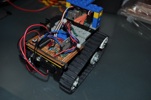
For more detail: PIC RC Motor Controller (and example lego robot)