Calculator Test using PIC24FJ64GA006 with Proteus Simulation

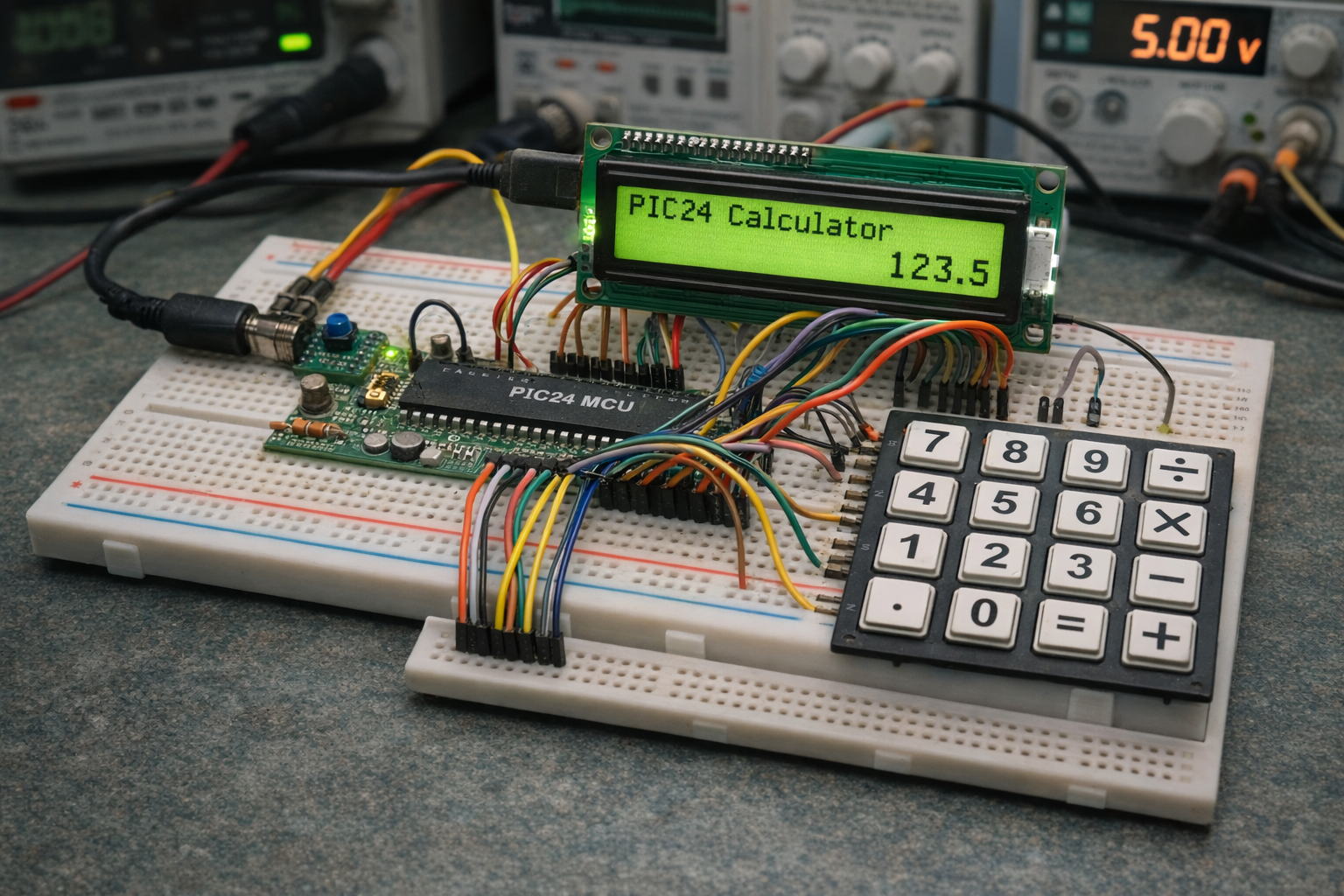
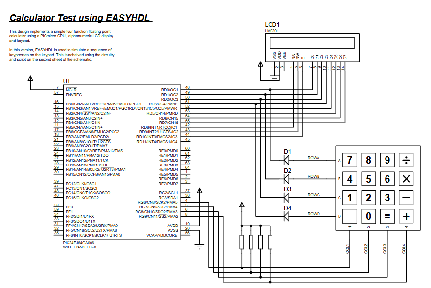
Summary of Calculator Test using PIC24FJ64GA006 with Proteus Simulation


This article details a practical embedded systems project: a calculator built using the PIC24FJ64GA006 microcontroller and simulated in Proteus. It utilizes a 4x4 matrix keypad for input and an LCD for output, processing real-time arithmetic operations like addition, subtraction, multiplication, and division. The firmware includes error handling for scenarios such as division by zero and supports floating-point numbers. Ideal for educational purposes, this project demonstrates effective human-machine interfacing and modular firmware design within an embedded environment.

Parts used in the Calculator Test using PIC24FJ64GA006 with Proteus Simulation:

  • PIC24FJ64GA006 Microcontroller
  • 16x2 LCD (LM020L compatible)
  • 4x4 Matrix Keypad
  • Pull-up resistors
  • Diodes
  • Power supply

Introduction

The Calculator Test using EASYHDL is a practical microcontroller project built on the PIC24FJ64GA006 and simulated in Proteus. This project demonstrates how a keypad-based calculator can be implemented using embedded systems concepts.

It uses a 4×4 matrix keypad for input and a 16×2 LCD display for output, making it a great example of DIY electronics and human-machine interfacing. The system processes arithmetic operations in real-time and displays results instantly. This project is ideal for understanding Proteus simulation, firmware logic, and practical electronics design.

PIC24 Calculator Project is a practical microcontroller project built using the PIC24FJ64GA006, featuring an LCD display and keypad input with Proteus simulation.

PIC24 breadboard calculator with LCD and keypad
Illustrative View of the Concept.

How the Project Works (Overview)

The calculator works by continuously scanning the keypad for user input. Each pressed key is interpreted either as a number or an operator.

  • Numeric inputs are stored in a buffer
  • Operators trigger arithmetic calculations
  • The result is formatted and displayed on the LCD

The firmware maintains:

  • Left operand (lvalue)
  • Right operand (rvalue)
  • Last operator (lastop)

When = is pressed, the system computes and shows the result. Error handling is included for cases like division by zer

Workflow Explanation

Based on the schematic and code logic:

  1. Keypad Input (4×4 Matrix)
    • Rows driven by MCU
    • Columns read with pull-up resistors
  2. Microcontroller Processing
    • Key scanning
    • Input buffering
    • Arithmetic computation
  3. LCD Output
    • Commands and data sent via PORTD
    • Displays numbers and results
  4. Control Flow
    • Infinite loop polling keypad
    • Decision: digit or operator
    • Execute operation → update display

Key Features

  • Real-time calculator using keypad input
  • Supports + , − , × , ÷ operations
  • Floating-point number handling
  • Error detection (division by zero)
  • LCD-based user interface
  • Efficient keypad scanning algorithm
  • Clean firmware structure using modular functions

Components Used

From schematic and source code:

  • PIC24FJ64GA006 Microcontroller
  • 16×2 LCD (LM020L compatible)
  • 4×4 Matrix Keypad
  • Pull-up resistors (for keypad columns)
  • Diodes (row isolation in keypad)
  • Power supply

Applications

This type of embedded systems project can be used in:

  • Educational calculator systems
  • Industrial control panels
  • Embedded UI systems
  • Digital instrumentation
  • Learning microcontroller project design
  • Custom input-output interfaces

Explanation of Code (High-Level)

Core Modules:

  • Keypad Interface
    • Scans rows/columns to detect key press
    • Returns ASCII value of pressed key
  • LCD Driver
    • Sends commands/data using PORTD
    • Handles busy flag and display control
  • Calculator Engine
    • Stores operands and operators
    • Performs arithmetic operations
    • Formats output for display
  • Main Control Loop
    • Continuously reads input
    • Updates display dynamically

Source Code

/******************************************************************************            
************                 LABCENTER ELECTRONICS                  ************            
************           Proteus VSM Sample Design Code               ************            
************                   MPLAB C30 'C' Calculator             ************            
*******************************************************************************/       

#include "p24FJ64GA006.h"
#include "calc.h"
#include "stddef.h"
#include "math.h"
#include "stdlib.h"
#include "string.h"

_CONFIG1(FWDTEN_OFF);
_CONFIG2(FNOSC_FRC&POSCMOD_NONE);

//Variables
static FLOAT lvalue = 0;
static FLOAT rvalue = 0;
static CHAR lastop;

Proteus Simulation

In Proteus simulation, the system behaves like a real calculator:

  • Pressing keypad buttons inputs numbers/operators
  • LCD updates instantly with typed values
  • On pressing =, result is displayed
  • Error message appears for invalid operations

This makes it an excellent virtual testing environment before hardware implementation.

Conclusion

This PIC24 calculator project is a solid example of combining Proteus simulation, keypad interfacing, and LCD control in embedded systems. It demonstrates real-world firmware design, modular coding, and hardware interaction.

Whether you’re learning or building practical DIY electronics, this project provides a strong foundation in microcontroller-based system design.

Quick Solutions to Questions related to Calculator Test using PIC24FJ64GA006 with Proteus Simulation:

  • What components are required for the calculator project?
    The project uses a PIC24FJ64GA006 microcontroller, a 16x2 LCD, a 4x4 matrix keypad, pull-up resistors, diodes, and a power supply.
  • How does the system handle user input?
    The system continuously scans the 4x4 matrix keypad where rows are driven by the MCU and columns are read with pull-up resistors.
  • Can the calculator perform division by zero?
    No, the system includes error handling that displays an error message when division by zero is attempted.
  • Does the calculator support floating-point numbers?
    Yes, the calculator engine handles floating-point number inputs and calculations.
  • Which software is used to simulate this project?
    The project is designed using EASYHDL and simulated in Proteus VSM.
  • What happens when the equals button is pressed?
    When = is pressed, the system computes the result based on stored operands and operators and updates the display instantly.
  • How is the LCD controlled in the code?
    LCD commands and data are sent via PORTD, which handles the busy flag and display control.
  • What types of arithmetic operations are supported?
    The calculator supports addition, subtraction, multiplication, and division operations.

About The Author

Ibrar Ayyub

I am an experienced technical writer holding a Master's degree in computer science from BZU Multan, Pakistan University. With a background spanning various industries, particularly in home automation and engineering, I have honed my skills in crafting clear and concise content. Proficient in leveraging infographics and diagrams, I strive to simplify complex concepts for readers. My strength lies in thorough research and presenting information in a structured and logical format.

Follow Us:
LinkedinTwitter