Summary of PIC Microcontroller-Based IC Tester for Efficient Integrated Circuit Verification
The article describes a portable, low-cost IC tester built around a PIC16F877A microcontroller and an HD44780 16x2 LCD. It tests digital and analog ICs via a ZIF socket by supplying inputs, reading outputs, and comparing results to truth tables in firmware. Results (Good/Bad/Error) display on the LCD. The system is software-expandable to support more ICs and can use a master-slave microcontroller setup for higher pin counts.
Parts used in the IC Tester:
- PIC16F877A microcontroller
- HD44780 16x2 LCD display
- Zero Insertion Force (ZIF) socket
- Power supply (5V for IC inputs and controller)
- PCB and microcontroller board
- Control switches/lever for ZIF socket
- LED power indicator
- Interconnect wiring and connectors
- Optional second microcontroller for master-slave configuration
1. INTRODUCTION
Within the electronics industry[1], as circuit complexity undergoes a drastic increase and the demand for higher reliability rises, a significant factor contributing to overall costs is the expense incurred during testing. Traditionally, distinct hardware circuits are required for testing different integrated circuits (ICs). Whether testing logic gates, flip-flops, or shift registers, each type of IC necessitates a specific tester, leading to increased circuit complexity and prolonged execution times.
The primary objective of an IC tester is to swiftly assess an IC’s functionality within a short timeframe. In the event of any discrepancies in the results, the tester identifies which gates are functioning correctly and which ones are faulty. The manual approach, involving human intervention, requires testing each individual IC by establishing necessary connections and verifying outputs for each gate based on the truth table. This method proves to be time-consuming and laborious.
The IC to be tested is positioned in the Zero Insertion Force (ZIF) socket. Inputs are supplied to the IC and processed through the slave-controlled board. The program is designed to compare the expected data from the truth table with the data obtained from the data bus. Ultimately, the LCD display presents the status of the IC, indicating whether it meets the expected conditions or not.
2. LITERATURE SURVEY
The implementation of the Digital IC tester [2] serves the purpose of testing digital ICs to identify faulty gates and acceptable gates. The microcontroller IC provides the necessary input to the gates of the IC under test [3], which is positioned in the ZIF socket. The corresponding outputs are collected and transmitted back to the same controller IC. Here, the output is compared with the functional or logic table, and any discrepancies trigger the display of faults on both the LCD display screen and the PC screen. The integration of microcontroller units with a PC streamlines the process of receiving data for the respective gates, processing the output, and displaying the results [4]. The functionality of a PC-based [5] controller is primarily determined by its program. A key advantage of this circuit is its ability to test new ICs without requiring additional hardware; a simple software update suffices for the task.
3. PROPOSED SYSTEM
The IC tester, built with the PIC 16F877A microcontroller and a display unit, is both cost-effective and user-friendly. Its programmable nature enables the testing of a diverse range of ICs, encompassing simple logic gates from the 74 series and linear circuits like LM741, IC555, and NE565. The test results are conveniently presented on the LCD display, indicating whether the tested IC is in good or bad condition. Notably, this IC tester is portable, making it a convenient and easy-to-use tool for electronic testing purposes.
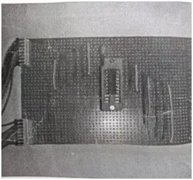
Hardware
The individual elements of the IC tester are elaborated upon as follows:
Display Unit
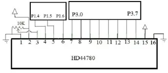
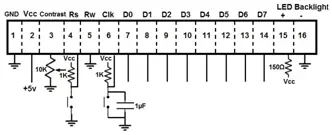
For presenting the outcomes and facilitating user interaction, we employ an HD44780 Liquid Crystal Display. This LCD features two lines and is equipped with 16 input pins. Figure 1 illustrates the connection of these pins to the microcontroller block.
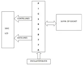
Microcontroller Unit
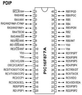
To implement this device, we utilize the PIC 16F877A microcontroller. The establishment of connections between various pins of the microcontroller and the peripherals enables the controller to monitor both analog and digital integrated circuits (ICs). The initial 32 bytes of the register space are dedicated to special purpose registers, while the remaining 96 bytes are allocated for general-purpose RAM.
PORT A serves as an input to the IC’s input pin and directs the corresponding output to the display. PORT B features an interrupt-on-change capability. PORT C plays a role in determining the functions of its pins. PORT D functions as an 8-bit parallel slave port. PORT E is employed for control signals. Additionally, the microcontroller incorporates timer modules to enhance its capabilities.
Software
The microcontroller carries out the program stored in its Flash memory, implementing the tester’s operation through a straightforward C program. The utilization of switch-case conditional statement loops allows the identification of the IC number on the provided list. Upon identifying the IC number, the input supplied to the IC at 5 volts is employed to generate the output, verifying the corresponding matched sequence of properties for the respective IC. The programming’s flexibility enables an increase in the number of IC components that can be tested. Being an EEPROM (Electrically Erasable Programmable Read-Only Memory) type of flash memory, any ambiguities can be easily addressed through simple modifications to the program stored in the controller.
Flow Chart
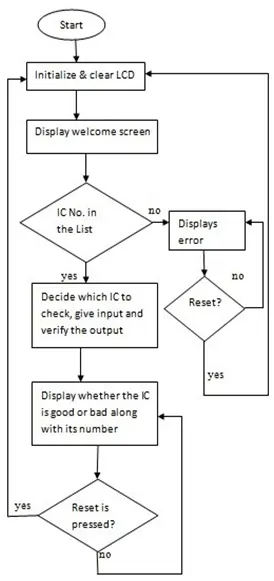
The flow chart details the sequence of actions, beginning with the activation of the power supply. Following this, the LCD display screen undergoes initialization, clearing the screen and subsequently presenting the welcome screen. Once the integrated circuit (IC) is inserted into the socket, the controller examines the IC number against the provided list, supplying the appropriate input to the IC. The controller then assesses and verifies the results before displaying the condition, indicating whether it is deemed good or bad.
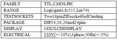
Technical Specification
4. WORKING DESCRIPTION
The operation of the device can be explained as follows: when the power supply is activated, the power LED illuminates. The Integrated Circuit (IC) under testing is inserted into the Zero Insertion Force (ZIF) socket and secured using the lever. Upon locking the IC in place, the LCD display indicates the IC’s status, displaying whether it is classified as “Good” or “Bad,” along with the corresponding IC number. If the IC is not properly seated, an “Error” message is displayed.
The controller program is structured using a switch-case concept, ensuring that when a specific IC matches the PIN number, the corresponding loop is executed. For digital ICs, the tester generates 0’s and 1’s as inputs, cross-checking them with the Truth table for the respective IC and displaying the resulting condition. For analog ICs, the device checks the input supply parameters, including VCC, Ground, and Output pins.
5. RESULT/EXPERIMENTALOBSERVATIONS
• Upon activating the power supply, the LCD screen will showcase the WELCOME text, as illustrated in Figure 8.

• Once the IC is inserted into the ZIF socket, the processor generates the necessary input to assess and identify the IC, providing both the identification number and indicating its condition.
As an illustration, when an OR gate IC (7432) is inserted into the socket, the LCD screen exhibits the IC number 7432 and indicates the condition of the IC, whether it is in a good or bad state. In the event that the IC is functioning well, the display corresponds to the depiction in Figure 9.

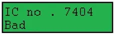
• If the IC is malfunctioning, the display unit will indicate a defective condition for the IC (7404), as depicted in Figure 10.
• In the case of an analog IC, the output assessment is akin to that of a digital IC. For instance, IC555 undergoes testing by examining the supply pin, ground, and the output pin. Subsequently, the observed conditions are presented as illustrated in Figure 11.

6. CONCLUSION
The Integrated Circuit Tester is designed to test both digital and analog ICs, eliminating the necessity for an external keypad. It can effortlessly accommodate a vast array of ICs as long as the memory capacity allows for it. The expansion of its capabilities does not require rewiring; rather, a simple adjustment of the source code suffices.
For scenarios involving a higher number of pins, a master-slave connection with two microcontrollers can be employed. One microcontroller is dedicated to the testing process, while the other manages the display unit. This configuration allows for efficient testing and display functions without the need for rewiring, only necessitating modifications to the source code for adaptation.
- What microcontroller is used in the IC tester?
The PIC16F877A microcontroller is used. - How does the tester display the test results?
Test results are shown on an HD44780 16x2 LCD display indicating Good, Bad, or Error. - Can the tester handle both digital and analog ICs?
Yes, it tests both digital ICs by comparing outputs to truth tables and analog ICs by checking supply, ground, and output pins. - How are ICs inserted into the tester?
ICs are placed into a Zero Insertion Force socket and secured with a lever. - Does adding new ICs require hardware changes?
No, adding support for new ICs requires only updating the controller program in flash memory. - What happens if an IC is not properly seated?
The LCD displays an Error message if the IC is not properly seated. - How does the tester generate inputs for digital ICs?
The microcontroller supplies 0s and 1s as inputs according to the programmed test sequences and compares outputs to the truth table. - Is the system portable and user-friendly?
Yes, the device is described as portable, cost-effective, and easy to use. - How can the tester handle ICs with more pins?
A master-slave configuration with two microcontrollers can be used to accommodate higher pin counts without rewiring.