Summary of HIGH ACCURACY CURRENT SENSOR WITH 400KHZ BANDWIDTH USING ACS37002
This project is a high-accuracy Hall-effect current sensor based on the Allegro ACS37002 IC with a 0.85 mOhm integrated conductor. It provides selectable gains (30–60 mV/A), a centered 2.5 V output, fast overcurrent alert (1 µs), wide bandwidth (up to 400 kHz), and low error/offset for measuring ±33 A to ±66 A. It runs from 5 V, uses a 6-pin CN2 connector for power and signals, and a protected overcurrent output configurable via a resistor divider.
Parts used in the High Accuracy Current Sensor Project:
- ACS37002 IC (Allegro)
- PCB (42.55 x 41.59 mm)
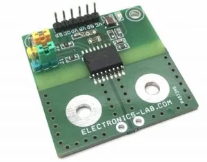
- CN2 6-pin header connector
- CN1 current source connector (5 mm ring terminal with 4 mm screws and nuts)
- Jumper headers J1 and J2 (for gain selection)
- D1 power LED
- Resistors R4 and R5 (resistor divider for overcurrent threshold)
- Supply decoupling and supporting passive components (as required on board)
This is a high accuracy current sensor project build using ACS37002 IC from Allegro, which is a fully integrated Hall-effect current sensor with 0.85mOhms integrated conductor. A fast overcurrent alert output, programmable gain settings and analog linear voltage outputs are key features of this project. The sensor has optimized accuracy for current ranges +/-33A to +/-66 A and the analog voltage output is linear for the current of this range. The operating voltage of the project is 5V DC. The output voltage of this sensor is centered at VCC/2 =2.5V. Output sensitivity depends on the jumper settings, please refer to the table below for sensitivity/Gain configuration. CN2 6-pin header connector provided for power input and outputs. D1 is the power LED. Overcurrent alert is set to a minimum but it can be set as per user requirement by changing resistor divider R4 and R5, more information provided below.
CONNECTOR CN2 CONNECTIONS DETAILS
- Pin1=VCC 5V DC
- Pin2=GND
- Pin3= VREF 2.5V For ADC (Can be used for Microcontroller Interface Left Unused for Stand Alone Use)
- Pin4=Sensor Voltage Output
- Pin5= Over Current/Fault Output
Connector CN1 = Current Source Connections (Use 5 mm Ring Terminal with 4 mm Screws and Nuts)
FEATURES
- Operating Supply 5V DC
- Output-VO 40mV/A, 50mV/A, 60mV/A, 30mV/A (50A,40A,33.3A,66.7A)
- Four Configurable Gain Settings Using Jumper J1, J2
- Adjustable Fast Over Current Fault 1us Response Time
- Over Current Output Normally High Goes Low @ Fault Condition (OCF)
- High Operating Bandwidth for Fast Control Loops
- 400Kz Frequency Bandwidth, 2us Response Time
- Very Low Sensitivity Error 1%
- 6mV Maximum Offset Voltage Over Temperature
- PCB DIMENSIONS 42.55 X 41.59 mm
Read more: HIGH ACCURACY CURRENT SENSOR WITH 400KHZ BANDWIDTH USING ACS37002
- What is the operating supply voltage for the project?
The operating supply voltage is 5V DC. - What is the sensor output centered voltage for ADC interfacing?
The output is centered at VCC/2 which is 2.5V. - What current ranges does the sensor optimize accuracy for?
The sensor has optimized accuracy for current ranges ±33A to ±66A. - How can I change the output sensitivity or gain?
Output sensitivity depends on jumper settings J1 and J2; selectable gains include 30, 40, 50, and 60 mV/A. - How is the overcurrent alert configured?
Overcurrent alert is set to a minimum by default and can be adjusted by changing the resistor divider R4 and R5. - What is the overcurrent alert behavior and response time?
The overcurrent output is normally high and goes low on fault; it has a 1 microsecond response time. - Which connector provides power and outputs?
CN2 is the 6-pin header connector for power input and outputs. - What are the CN2 pin functions?
CN2 pins: Pin1 VCC 5V, Pin2 GND, Pin3 VREF 2.5V, Pin4 Sensor Voltage Output, Pin5 Over Current/Fault Output. - What is the PCB size of the project?
The PCB dimensions are 42.55 x 41.59 mm. - What bandwidth and response characteristics does the sensor provide?
It provides up to 400 kHz bandwidth and 2 microsecond response time for general operation, with a fast fault response of 1 microsecond.