Summary of LCD OSCILLOSCOPE CIRCUIT PROJECT PIC18F4520
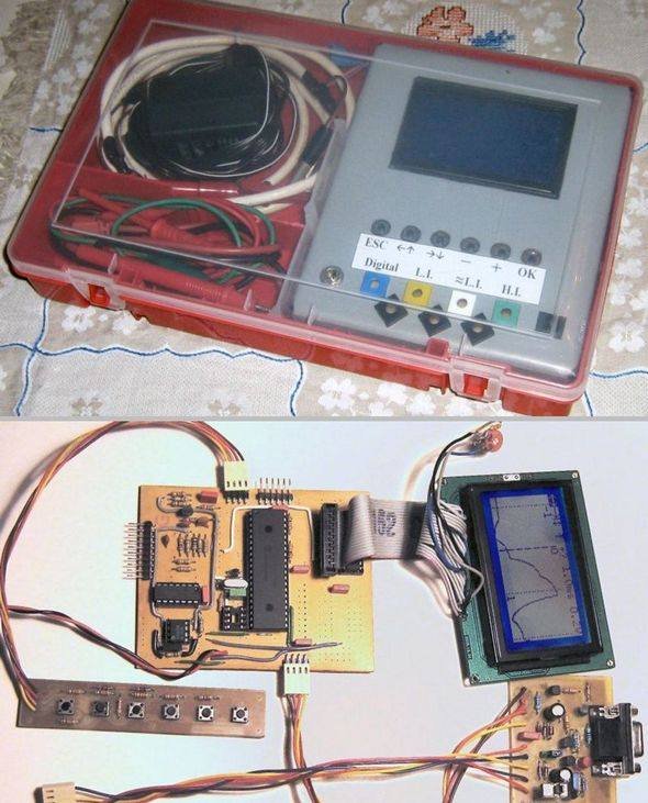
This project describes a PIC18F4520 microcontroller-based oscilloscope circuit featuring a 128×64 LCD display. It includes PCB schematics, source code files such as menu.c and glcd.c, and instructions for installing a bootloader hex program. The design allows users to build a compact oscilloscope interface for signal visualization using the microcontroller and graphical LCD.
Parts used in the LCD Oscilloscope Circuit Project PIC18F4520:
- PIC18F4520 microcontroller
- 128×64 Graphic LCD (GLCD)
- Printed Circuit Board (PCB)
- Bootloader hex program
- Supporting passive components (resistors, capacitors)
- Power supply components
- Interface connectors (for LCD and input signals)
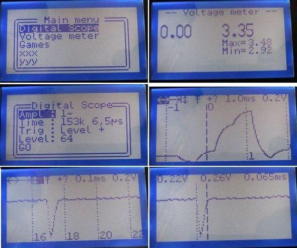
Oscilloscope circuit PIC18F4520 microcontroller based on the indicators used for the 128×64 LCD PCB schematics and source code for the project given all menu.c, etc. glcd.c. in different projects such as files can be... Electronics Projects, LCD Oscilloscope Circuit Project PIC18F4520 “microchip projects, microcontroller projects, “
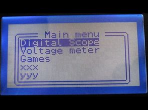
Oscilloscope circuit PIC18F4520 microcontroller based on the indicators used for the 128×64 LCD PCB schematics and source code for the project given all menu.c, etc. glcd.c. in different projects such as files can be useful also to install the bootloader hex program and the circuit shown in Diagram.
Source: LCD OSCILLOSCOPE CIRCUIT PROJECT PIC18F4520 alternative: lcd-oscilloscope-circuit-project-pic18f4520.rar alternative link3