


Summary of 12F675 Tutorial 5 : A Temperature data logger using PIC EEPROM. using pic microcontroller
This PIC microcontroller project functions as a temperature data logger, storing readings from an LM35DZ IC into the internal EEPROM of a 12F675 chip. It captures 64 temperature values at set intervals, indicated by LED flashes, and signals a full storage buffer with a permanent LED light. The system allows users to read stored data via a serial port or erase the memory through a specific power-cycle sequence.Parts used in the Temperature Data Logger:
- PIC 12F675 Microcontroller
- LM35DZ Temperature Sensor IC
- LED Indicator
- Blue Wire (Switch/Button)
- Diode (D2)
- Resistor (R6)
- Solderless Breadboard
EEPROM is useful for storing long term data such as data logger information and this PIC microcontroller EEPROM project saves the temperature from an LM35DZ IC to the PIC's internal long term data storage area. The project follows on from the last project using the virtually the same hardware.
It stores temperature readings internally at regular intervals until full and after this it turns on the LED. The LED is really just for showing that something is happening and in a real data logger you would not use it.
 Jump to Solderless breadboard.
Jump to Circuit Diagram.
Jump to Software.
Note: This project is not optimized for power consumption so the best way to use it is powered from a power block. The current consumed is about 13mA (LED off) 16mA (LED on at end). If you want to use a battery use a rechargeable PP3 and do not attach the LED.
The 12F675 may not the best PIC microcontroller to use for low power data logging and a better choice would be the 16F88 as it can change its internal oscillator on the fly going into slow (current saving) mode. But you could use the 12F675 with a slow external 32kHz crystal.
At every ADC reading the LED is flashed briefly and when you select a 500ms reading interval you can see the readings being taken. When 64 readings are accumulated the LED is lit permanently - showing that the data store is full.
Note: For this chip you only get to store 64 results as you need to store an unsigned integer for every ADC result and this takes 2 bytes so 128 Bytes/2 = 64 results.
You can hit the button at any time and the contents of the EEPROM will be read from the internal EEPROM and transmitted to the PC via the serial port.
To erase the internal EEPROM hold the button and cycle the power - this flashes the led 6 times indicating erase (normal startup flashes the LED 3 times).
Solderless breadboard
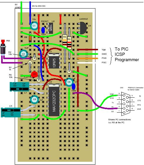
The solderless breadboard and circuit diagram are nearly the same as used in the previous project so if you have already built it you don't need to do any more. Just add the blue wire, D2 and R6.
Circuit diagram
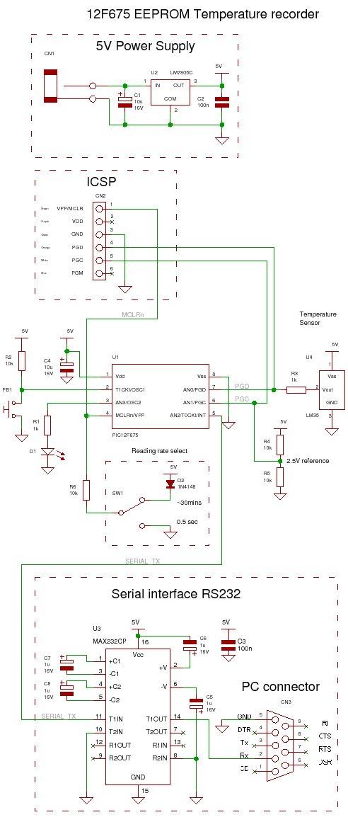
Note that the switch shown below is just a blue wire above. Either leave the blue wire where it is to hold the input, at pin 4, high or move the top of the blue wire to ground (0V - green wires at top left - on the left of the solderless breadboard) to set GP3 (pin 4) low.
Note: The diode stops the programming voltage conflicting with the 5V power supply - reversed biased when the high programming voltage is present.
For more detail: 12F675 Tutorial 5 : A Temperature data logger using PIC EEPROM.
Quick Solutions to Questions related to Temperature Data Logger:
- How many temperature readings can this project store?
The project stores exactly 64 results because each unsigned integer takes 2 bytes within the 128-byte EEPROM. - What indicates that the data store is full?
The LED turns on permanently after 64 readings are accumulated to show the memory is full. - Can I use a battery for this project?
You can use a rechargeable PP3 battery, but you should not attach the LED to save power. - How do I erase the internal EEPROM?
Hold the button and cycle the power; the LED will flash 6 times to confirm the erase. - How do I read the stored data?
Hit the button at any time to transmit the contents of the EEPROM to the PC via the serial port. - Is this design optimized for low power consumption?
No, the project is not optimized for power and is best powered from a power block. - Which microcontroller is better for low power data logging?
The 16F88 is a better choice than the 12F675 because it can change its internal oscillator to slow mode. - What is the current consumption when the LED is off?
The current consumed is about 13mA when the LED is off.
Related projects
Spectrum Analyzer using TMS320F28023DA with Proteus Simulation
Introduction This project demonstrates a real-time audio spectrum analyzer using the TMS320F28023DA Piccolo microcontroller, simulated in Proteus VSM. The system captures an...
Sensors & TemperatureDHT22 Low Cost Humidity Sensor using PIC18F25K20 with Proteus Simulation
IntroductionThis microcontroller project demonstrates how to interface a DHT22 (RHT03) digital temperature and humidity sensor with a PIC18F25K20 using Proteus simulation.The project...
Sensors & TemperatureCrafting a Microcontroller-Based Temperature Monitoring System
Abstract As technological advancements progress, processes become increasingly intricate, demanding a corresponding expansion in the parameters necessary for efficient analysis. Data acquisition,...
Sensors & TemperatureAutomated Room Temperature Monitoring System using Microcontrollers
Abstract Monitoring the temperature within a computer server room stands as a crucial responsibility to uphold the server's performance amidst potential disruptions...
Sensors & TemperatureInnovative Approaches to Control System Design for 100KV Impulse Generators
1. INTRODUCTION An impulse generator is an electrical device designed to generate short-duration surges of high voltage or high current. Impulse signals...
Sensors & TemperatureSmart Baby Incubator: Enhancing Care with PIC Microcontrollers
INTRODUCTION Within the effective Baby Incubator system, the incubator serves as an infant-stimulation apparatus designed for the intensive care of newborns, particularly...

Ibrar Ayyub
I am an experienced technical writer holding a Master's degree in computer science from BZU Multan, Pakistan University. With a background spanning various industries, particularly in home automation and engineering, I have honed my skills in crafting clear and concise content. Proficient in leveraging infographics and diagrams, I strive to simplify complex concepts for readers. My strength lies in thorough...