


Summary of Rotary Encoders
Rotary encoders provide durable, digital rotational input without ADCs and can represent multiple input types when paired with a feedback display. This project uses a 24-position rotary encoder with 16 LEDs in a circle, driven by an A6276 16-LED serial driver and a PIC16F7550 microcontroller. The encoder's A and B outputs connect to RB4 and RB5 on the PIC using internal PORTB weak pull-ups and interrupt-on-change for reliable detection; the encoder common (C) is grounded.Parts used in the Rotary Encoder Display Project:
- 24-position rotary encoder (3-pin: A, B, C)
- 16 LEDs arranged in a circle
- A6276 16-LED serial driver IC
- PIC16F7550 microcontroller
- Wiring/connectors
- Ground connection for encoder C pin
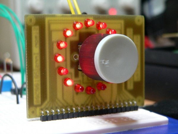 When using rotational encoders in projects it's possible to use the same encoder to represent a number of different input types, however this requires some form of feedback display to let the user know what information he is inputting and the 'position' of the encoder. The project is based around a 24 position rotary encoder, 16 LEDs arranged in a circle around the encoder, an A6276 16 LED serial driver IC and the PIC182550 microcontroller. A rotary encoder has 3 pins usually called A, B and C. The C pin (which is normally the centre pin) should be grounded and both A and B should be connected to the microcontroller with individual pull-up resistors on each input. In this project I used RB4 and RB5 on the PIC to connect the encoder; this has 2 advantages, firstly you can use the PORTB internal weak pull-up (which means you do not need external resistors) and also the PIC provides an 'interrupt-on-change' which can be used to monitor the encoder.
Build Accurate LC Meter and start making your own coils and inductors. This LC Meter allows to measure incredibly small inductances making it perfect tool for making all types of RF coils.  LC Meter can measure inductances starting from 10nH - 1000nH, 1uH - 1000uH, 1mH - 100mH and capacitances from 0.1pF up to 900nF. The circuit includes an auto ranging and reset function to make sure the readings are as accurate as possible .
For more detail: Rotary Encoders
Quick Solutions to Questions related to Rotary Encoder Display Project:
- How is the encoder common pin connected?
The C pin (centre pin) should be grounded according to the article. - Which PIC pins are used for the encoder inputs?
The article uses RB4 and RB5 on the PIC to connect the encoder. - Do the encoder inputs require external pull-up resistors?
No, using RB4 and RB5 allows use of the PORTB internal weak pull-up so external resistors are not needed. - What advantage does the PIC provide for monitoring the encoder?
The PIC provides an interrupt-on-change feature on PORTB which can be used to monitor the encoder. - How many LED positions are used around the encoder?
16 LEDs are arranged in a circle around the encoder in this project. - Which LED driver IC is used?
The project uses an A6276 16 LED serial driver IC. - What resolution rotary encoder is used?
The project is based around a 24-position rotary encoder. - Why use a rotary encoder instead of an analogue potentiometer?
Rotary encoders are digital, do not wear down like analogue potentiometers, and provide digital positioning without ADCs according to the article.
Related projects
Real-Time CAN-Based Vehicle Monitoring System with PIC MCU
INTRODUCTION The Controller Area Network (CAN) is a robust vehicle communication bus standard that was primarily developed for automobile applications but has...
Motors & RoboticsEasy Way to Learn Robotics Using Microcontrollers: A Beginner’s Guide
The title, "Easy Way to Learn Robotics Using Microcontrollers," promises an accessible entry point for those curious about the exciting world of...
Motors & Robotics · PIC16F877AEfficient Sun-Following Robot: A Solar Tracker with Microcontroller Control
Abstract The impending global challenge of dwindling non-renewable fuel resources underscores the urgency of transitioning towards renewable energy alternatives like solar power....
Motors & RoboticsInnovative Robotics: A Comprehensive Project Exploration
A DC motor functions as an electromechanical device, translating electrical signals into mechanical movements. The rotation of the motor correlates directly with...
Motors & RoboticsAdvanced Techniques for Fault Detection, Indication, and Protection in Induction Motors
1. INTRODUCTION The impact of microcontroller usage on our daily lives is remarkable. This versatile device is now prevalent in various control...
Motors & RoboticsExploring Versatility: GSM-Based Robotic Vehicle Technology
Introduction To Robotics The term 'Robot' remains elusive, defying a precise definition due to its evolving usage. Initially, it referred to humanoid...

Ibrar Ayyub
I am an experienced technical writer holding a Master's degree in computer science from BZU Multan, Pakistan University. With a background spanning various industries, particularly in home automation and engineering, I have honed my skills in crafting clear and concise content. Proficient in leveraging infographics and diagrams, I strive to simplify complex concepts for readers. My strength lies in thorough...