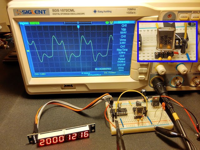
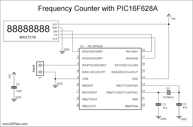
Couple of weeks ago I purchased from eBay one of these amazingly cheap an useful modules with MAX7219 LED driver and 8 digit LED display. It is ideal for frequency counter project. The problem was the absence of library for PIC microcontrolers. Luckily, I found a great library for Arduino and I reworked it to be compatible with PIC. The schematic of the frequency counter is actually almost the same as the previous . It uses PIC16F628A microcontroller with external 32.768kHz watch crystal attached to Timer1 to generate 1 second time base. Measured signal is fed to pin3 (RA4) which is counted by Timer0.
The program make short (0.125s) test of the input signal to determine the prescaler value. Next is the actual counting with the proper prescaler value and then the result is send to the display.
This is fast breadboard proof-of-concept project, and I don’t intend to make a finished product, for now at least. Of course there must be some sort of preamplifier/protection in front of the frequency counter in order to be usable.
In the pictures below is shown the breadboard and five different quartz crystals generating different frequencies. The differences between the value on the display and the value on the oscilloscope are negligible. I tested the schematic also with frequencies above 90 MHz and even above 100Mhz and the results was accurate, but of course most significant digit was lost in case of 100+ MHz.
Schematic
For more detail: 100MHz frequency counter with PIC16F628A – LED Display


