You can use this Universal Infrared Receiver (UIR) project to control your PC:
- Starting Windows programs,
- setting the Windows volume control,
- even moving the mouse around the screen!
All at the touch of a button – with your TV remote control in fact!
It uses a PIC microcontroller to characterize the demodulated infrared signal and then transmit it as a serial data stream to the PC.
Software running on the PC recognizes data stream for each key press (in fact the PC software has to learn the data stream for each key press) and activates the program (or event) that you specify. Since the software can learn each key press you can use it with any remote control e.g. TV, video, DVD, satellite etc.
It’s even good with multiple remotes so you could use any one of a set of remotes to control the PC
Specification for Serial Infrared receiver project.
| Baud Rate | 57600 Baud |
| Clock | Internal 8Mhz |
| Remove Control type | Any (Point any control at it and let the PC software learn its codes). |
Note: Some remote controls need two key presses (if you press the same key) as they output an inverted key sequence for a repeated key. If you press a different key then it works as a normal remote.
How the Serial Infrared receiver works
This project uses a standard Infrared detector module (one of those 3 pin devices) as the main input.
It’s not worth making your own circuit up as it will not match the performance of a three pin demodulator module.
I had a go using some circuits I found on the web and but these use a PIN diode and a high impedance amplifier e.g. LM3140 – but the circuits are actually light meters and saturate when a light shines on them (even desk lamp) – so they become insensitive to the IR light – the PIN diode reacts to any light source. You can get some use out of them up to about six feet but a lot of engineering has gone into the three pin modules so it really is worth using them and they are very cheap.
Inside the module is a PIN diode, AGC circuit, band pass filter, control logic and output detector. The datasheet specifies use from 15m (45ft) up to possibly 30m (90ft) max!. These are very good detectors that are also insensitive to sunlight (has a physical filter over the PIN diode and the electronic bandpass filter).
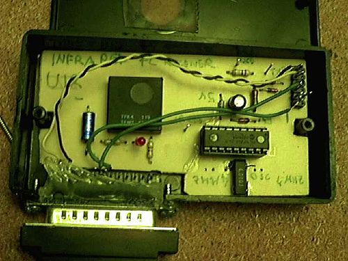
Serial Infrared receiver
How the Serial Infrared receiver works.
This project took longer than it should have and I have ended up with a far smaller source code than my initial attempts! First off I used the capture facility in the CCP and the Timer1 timer to accurately measure each period of high and low decoded IR. This turned out to be too accurate!
IR signal codes decoding accuracy
You don’t need accuracy in this project – IR codes are designed not to need accurate measurement and if you attempt it slight variations in the edge positions or measuring accuracy cause the output numbers to change. Since the decoder software in the PC relies on a repeatable data stream (with slight variation) this method does not work.
IR signals are designed so that you can sample them but this requires that you know the code sequence (or encoding e.g. RC5) in advance so that you can time from the start sequence to the exact middle of a bit position.
Since this project allows you to use any remote control unit, the encoding sequence can not be known in advance, so the the solution is to sample the remote control sequence at a high frequency.
The problem is that if you start decoding from the first rising edge then errors accumulate due to slight variations in the remote control output (or the sampling edge occurs at the same time as an input transition) causing a random data stream output which can not reliably be decoded by the PC software.
IR decode solution
The solution is to sample the input data starting from each rising and falling edge where a bit measurement period counter (period counter) is reset. At each sample point (here it is about 50us) the period counter is incremented. This gives a number that represents the period of each high or low part of the signal.
The 50us sample period is about ten times the expected signal period (IR codes generally use 500us minimum period) so this gives a good period measurement.
Note that the period counter is 8 bits long so that for long input sequences (high or low) the counter wraps around – this does not matter since the period counter will always produce the same value for the same input sequence and this is what the PC decoder software is looking for.
For more detail: Universal Serial Infrared Receiver using PIC16F88