This project of mine started because I wanted to learn how to layout my own printed circuit board (PCB). I needed a simple and easy-to-solder circuit, so I chose this one because who doesn’t love interactive LEDs?
In this Instructable I will only be showing the implementation of my circuit on a breadboard. In my next Instructable (now available here), I will demonstrate my process of designing and laying out the PCB.
As I mentioned I wanted a simple project and this one is just that! Students, hobbyists, and anyone else of all skill levels will be able to easily put this together. Let’s get started!
Step 1: Introduction to the Circuit
This step is the “How it Works” section. If you prefer to get right into making the circuit, skip to the next step.
If you’re still with me, I’m going to start with a brief introduction of some of the components I used in this circuit. (An exact list of materials is in the next step.)
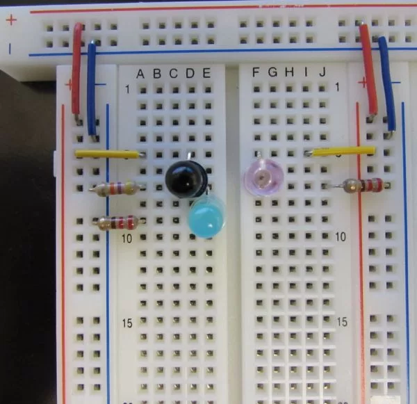
- The component that looks like a black LED is not actually an LED at all. It is a photo-transistor. How does a photo-transistor work? When the photo-transistor receives a certain wavelength of light, it “turns on” and allows current to flow through it. When the photo-transistor is not receiving that wavelength of light, it is “off”. That being said, the photo-transistor is essentially acting as a switch in our circuit. Note: The photo-transistor I used is made to respond best to light with a wavelength of 880nm.
- The pink LED in the image above is an infrared (IR) LED which does exactly what it sounds like it would do. Rather than emitting light that our eyes can see, it emits light in the infrared range of the electromagnetic spectrum. It is in series with a 220Ω current-limiting resistor to protect it from burning out. Note: The IR LED I used is made to emit light at a wavelength of 880nm. Sound familiar? I’ll get back to this in a bit.
- The blue LED is just that, a blue LED. It is also connected to a 220Ω current-limiting resistor.
- The only other components I used were resistors and wires.
So how does this all work? What makes it proximity-sensing? Remember in the explanation above that the photo-transistor acts like a switch. So when the photo-transistor is off, no current is flowing across it to our blue LED and the LED is off as well. Now look at the other side of our circuit. That’s where the IR LED is connected, and it is connected such that it is always on and emitting 880nm infrared waves. Remember that I also mentioned the photo-transistor is set to respond best to wavelengths of 880nm? That’s how the proximity-sensing works! When an object (such as your hand) goes over this little “cluster”, IR light of 880nm is emitted from the IR LED. This light reflects off of your hand and back to the circuit. When the photo-transistor picks it up, it turns on allowing current to flow through from the source to our blue LED lighting it up!
Note: The light we’re dealing with doesn’t have to specifically be 880nm to for this to work. The important thing is just that the photo-transistor responds best to the wavelength of light that the IR LED emits.
Step 2: Gather the Materials
This circuit consists of “clusters” that are in parallel. Since the clusters are in parallel, this means you can add as many as you want without the LEDs getting any dimmer! You could have 1000 clusters if you wanted to and every LED would be just as bright! (Your battery wouldn’t last very long though.) For my implementation I used 24.
For each cluster you will need:
- Photo-transistor
- IR LED
- LED of any color
- 2 x 220Ω resistors
- 47kΩ resistor
- A couple small wires
Note: Photo-transistors and IR LEDs are available at different wavelengths. You don’t have to use 880nm as I mentioned in the previous step. For best results though, use photo-transistors that are made to respond best to the wavelength that your IR LEDs emit.
For the rest of the circuit you will also need:
- A breadboard (I’m using 3. Use as many as you like!)
- A power source and connector (not pictured)
For a power source I’m using a 9V battery because I had one at my desk already. You have a lot of other options here though such as a 6V lantern battery or a 4 AA batteries.
Step 3: Connect Power Rails
I like to start by getting all of my power and ground rails connected. Just as you can see in the picture above I connected all of my positive (red) rails and negative (blue) rails. I also plugged in my battery connector, but I’m leaving the battery out until the end so there’s no current through the circuit while I’m building it.
Step 4: Build the first cluster!
I prefer to start with building one cluster to test my design.
Note: Remember that the photo-transistor is not an LED. However, since it looks like an LED I will refer to its pins as anode (+) and cathode (-) for simplicity. I also included an image above that shows how to determine which pin is the anode and which is the cathode. I also included the circuit schematic, an animated breadboard image, and a photo of my circuit for reference.
- Connect the “anode” of the photo-transistor to the positive power rail.
- Connect the 47kΩ resistor from the cathode of the photo-transistor to ground. This resistor acts as what’s called a pull-down resistor. It helps direct the current to where we want it to go.
- Also connect the cathode of the photo-transistor to the anode of the blue LED.
- Connect the cathode of the blue LED to ground with a 220Ω resistor.
- On the other side of the “valley” of the breadboard, connect the anode of the IR LED to the positive rail.
- Connect the cathode of the IR LED to ground with a 220Ω resistor.
If you would like, go ahead and connect your power source and test it out!
(If it’s not working, see the final step for troubleshooting procedures.)
For more detail: Proximity sensing LEDs