
Summary of Solar Tracking System
This article describes a low-cost, PIC microcontroller-based solar tracking system designed to maximize solar panel illumination. The prototype utilizes two unipolar stepper motors and four IR-850nm LEDs as light sensors. Built on a simple strip board frame, the system allows independent rotation in two axes (up/down, left/right) based on light intensity differences detected by the sensors. Although functional, the author notes limitations regarding the payload weight and motor torque, suggesting counterweights or gear reducers for future improvements.
Parts used in the Solar Tracking System:
- PIC microcontroller
- 2 unipolar stepper motors
- 4 IR-850nm LEDs
- Solar panel
- ULN2003A driver
- Strip board
- Connecting bolts
This is a simple PIC microcontroller based Solar Tracking system, only basic electronics skills are required. It uses 2 unipolar stepper motors and 4 IR-850nm LEDs as sensors to follow the sun maximizing solar panel illumination.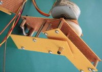
The entire prototype frame was built from simple, cheap and widely available strip board. Just cut it to a required size, widen the holes with screwdriver to fit connecting bolts and you’re done. If you want to build a similar circuits or use current configurations as a basis for more advanced design follow the pictures, hopefully it will give you some ideas. Here are some of the development steps taken from a standard strip board to a final design.
The assembly code is a modified version of original code from recently published Stepper Motor Interface PIC16F post. Now 2 step motors can independently rotate to any direction according to amount of light received by each IR LED. For example if Upper LED receives more light than the Lower LED PIC microcontroller will move the platform with mounted solar panel in the direction of stronger light source. Motor control is done by outputting coil switching sequence through ULN2003A.During the development a few limitations or “bugs” of current design were discovered. Although the payload platform can move in 2 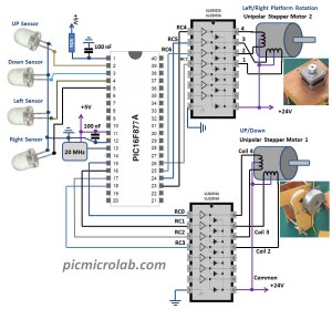 axis,(UP,Down,Left,Right) the solar cell attached to it is too heavy for stepping motor that was used to rotate it,if I had to build a new solar tracker I would change the center of mass or use counterweights for better balancing thus reducing the motor load, also direct frame connection to a platform rotating motor without some sort of reducer mechanism was a mistake, again the final design with solar cell attached weights too much and the motor doesn’t have enough torque to rotate it properly even with max allowed 24 V.UP/Down axis movements are working OK.Assembly/hex files available here.
For more detail: Solar Tracking System
- What components are used as sensors?
The system uses 4 IR-850nm LEDs as sensors to follow the sun. - How does the microcontroller control the motors?
Motor control is done by outputting coil switching sequences through the ULN2003A. - Can the platform move in multiple directions?
Yes, the payload platform can move in 2 axes which are up, down, left, and right. - What material was used to build the frame?
The entire prototype frame was built from simple, cheap, and widely available strip board. - Does the current design have any known limitations?
Yes, the solar cell attached is too heavy for the stepping motor used to rotate it. - What voltage was applied during development?
The motor did not have enough torque even with the max allowed 24 V. - How does the system determine movement direction?
If an LED receives more light than its counterpart, the PIC moves the platform toward the stronger light source. - What advice does the author give for future builds?
The author suggests changing the center of mass or using counterweights for better balancing.
