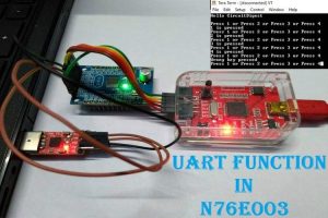
UART stands for Universal Asynchronous Receiver/Transmitter and it is a useful hardware feature in any microcontroller unit. A microcontroller needs to receive data, process it, and send it to the other devices. There are different types of communication protocols available in the microcontroller, however, UART is the most used one among the other communication protocols like SPI and I2C. If someone needs to receive or transmit data serially, UART is always the simplest and common option. The advantage of UART is it only requires two wires to transmit data between devices. Continuing with our Nuvoton Microcontroller Tutorial, in this article, we will learn how to perform serial communication using the N76E003 microcontroller.
Basics of UART Communication
Now, as we know what UART is, it is important to know the associated parameters of the UART.
Two UART devices receive and transmit data at the same frequency. When the receiving UART device detects a start bit, it starts to read the incoming bits at a specific frequency known as the baud rate. Baud rate is an important thing for UART communication and it is used to measure the speed of data transfer in bits per second (bps). This baud rate speed, for the transmit and receive, must be at the same baud rate. The baud rate speed difference between the transmitting and receiving UARTs can only be about 10% before the timing of bits gets too far off. Most popular baud rate speeds are 4800, 9600, 115200 bps, etc. Previously we have used UART communication in many other microcontrollers as well that are listed below.
- UART Communication between ATmega8 and Arduino Uno
- UART Communication between Two ATmega8 Microcontrollers
- UART Communication using PIC Microcontrollers
- UART Communication on STM8S Microcontroller
The N76E003 has two UARTs – UART0 and UART1. In this tutorial, we will use the UART peripheral on N76E003 microcontroller unit. Without wasting much time, let’s evaluate what kind of hardware setup we require for this application.
Hardware Requirement and Setup
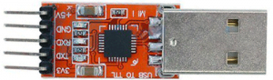
The major component that is required for this project is the USB to UART or TTL converter module that will make the interface required between the PC or Laptop with the microcontroller module. For this project, we will use CP2102 based USB to UART module that is shown below.
Not to mention, other than the above component, we need the N76E003 microcontroller based development board as well as the Nu-Link Programmer. An additional 5V power supply unit may be required if the programmer is not used as a power source.
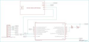
Circuit Diagram for Nuvoton N76E003 UART Communication
As we can see in the below development board schematic, the 2nd and 3rd pin of the microcontroller unit is used as a UART0 Tx and Rx respectively. On the extreme left, the programming interface connection is shown.
UART Pins on Nuvoton N76E003 Microcontroller
The N76E003 has 20 pins out of which 4 pins can be used for UART communication. The below image is showing the UART pins highlighted in a red square box (Rx) and Blue square box (Tx).
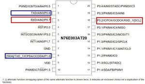
For the UART0, pin 2 and 3 are used for UART communication, and for the UART1, pin 8 and pin 18 is used for communication.
UART Registers in Nuvoton N76E003 Microcontroller
N76E003 has two enhanced full-duplex UARTs with automatic address recognition and framing error detection – UART0 and UART1. These two UARTs are controlled using registers categorized into two different UARTs. There are two pairs of RX and TX pins available in N76E003 for UART operations. Thus the first step is to select the desired UART port for operations.
In this tutorial, we will use the UART0, thus the configuration will be shown for the UART0 only. UART1 will have the same configuration but the registers will be different.
After selecting one UART (UART0 in this case), the I/O pins that are needed to be used for RX and TX communication needs to be configured as input and output. The RX pin of UART0 is pin 3 of the microcontroller that is Port 0.7. As this is a serial port receive pin, the Port 0.7 is needed to be set as input. On the other hand, the Port 0.6 which is the 2nd pin of the microcontroller is a transmit pin or output pin. It needs to be set as a Quasi bidirectional mode. These can be selected using the PxM1 and PxM2 register. These two registers set the I/O modes where the x stands for the Port number (For example, Port P1.0 the register will be P1M1 and P1M2, for P3.0 it will be P3M1 and P3M2, etc.) The configuration can be seen in the below image-
Source: UART Communication with Nuvoton N76E003 Microcontroller – Serial Communication