 Stepper motor due its excellent features is very famous in between hobbyist for various robotic applications. Running DC, Stepper motor and servo is the most basic requirement in any robotic application which moves. Stepper motor’s ability to run in various modes with various speed and torque gives it a more degree of advantage over the simple DC motor for various projects, especially in robotics based projects. – See more at: http://www.rakeshmondal.info/Stepper-Motor-Driver-PIC18F4550-Microcontroller#Stepper-Motor-Driver
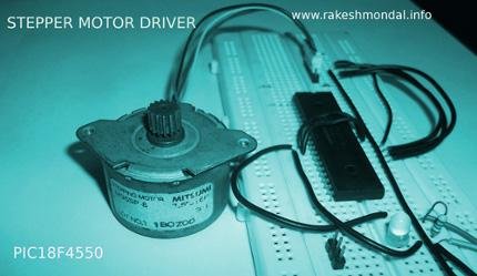
So in this basic stepper motor tutorial we will learn to drive a simple 5 wire unipolar stepper motor using a 40 pin PIC18F4550 microcontroller.
For a little more sophisticated Stepper motor Driver you can also follow my USB Stepper Motor Driver project which is quiet similar to current project , however this driver tutorial does not involve any interaction to any computer system directly except for writing the codes.
– See more at: http://www.rakeshmondal.info/Stepper-Motor-Driver-PIC18F4550-Microcontroller#Stepper-Motor-Driver
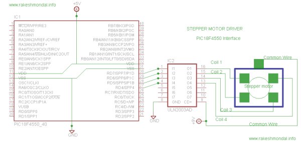
The stepper Motor can be also connected directly without ULN2003, but during the testing the results were not satisfactory hence a ULN2003 was added.
Caution!: 9V power supply is given to Stepper Motor which is not same as the voltage for the PIC18F4550 power supply (5V). Do not connect both the power supply together as the PIC18F4550 cannot bear more than 5V, both the supply must not be shot together or the microcontroller will be damaged.
If you have a single source of power supply for both the Stepper motor supply and Microcontroller, then add a MCP102 or an IC 7805 Voltage regulator (5v) before the VSS terminal of the Microcontroller, which would keep the input voltage to microcontroller at 5V.
The source code is compiled with MPLAB X IDE and X C8 Compiler which can be loaded into the microcontroller using pickit2 or JDM Programmer. It can be also compiled with Mplab and C18 compiler without much effort. For convenience I have added both versions of the source code at the end of this post with the compiled HEX file. For our Stepper Motor Driver we are not going to use any external Oscillator with the microcontroller.
There are two source code posted here, the source code 1 demonstrate the basic and simple Single Stepping mode of a stepper motor. The second source code is little more complex and has three other stepping modes (Single, FULL and HALF) cycling with delay of 5 seconds each.
The first code demonstrates Single stepping mode for driving our 5 wire unipolar stepper Motor. Where the Stepper Motor coils are connected to PIC18F4550 pins, RD4, RD5, RD6 and RD7.
You would also require a header file which contains the various compiler directives, which is common for both the source codes 1 and source code 2.The delay has been set to 50000 microsecond or 50 milliseconds.
 If in case if you want to use __delay_us( ); instead of __delay_ms( ); for adding delays then you can use some time converters or my favorite online scientific calculator ( eeweb calculator ) for ms to us conversion.
/* ****************** Steppermotor.c ****************** */
#include <p18f4550.h>
#include “headerzz.h”;
#define _XTAL_FREQ 2000000
void main(void)
{
TRISDbits.TRISD0=0; // Configuring Port D to output
TRISDbits.TRISD1=0; // From pins RD4 to RD7
TRISDbits.TRISD2=0;
TRISDbits.TRISD3=0;
while(1)
{
LATDbits.LATD0=1; // ON
LATDbits.LATD1=0;
LATDbits.LATD2=0;
LATDbits.LATD3=0;
__delay_ms(50);
LATDbits.LATD0=0;
LATDbits.LATD1=1; // ON
LATDbits.LATD2=0;
LATDbits.LATD3=0;
__delay_ms(50);
LATDbits.LATD0=0;
LATDbits.LATD1=0;
LATDbits.LATD2=1; //On
LATDbits.LATD3=0;
__delay_ms(50);
LATDbits.LATD0=0;
LATDbits.LATD1=0;
LATDbits.LATD2=0;
LATDbits.LATD3=1; // On
__delay_ms(50); } }
/* THE END */