PICMETER Introduction
This PICMETER project has grown into a useful and reliable tool for any electronics enthusiast.
- It runs on a PIC16F877 / 877A micro controller.
- It is a PIC development system
- It is 19-function multi-meter (voltmeter, frequency meter, signal generator, thermometer…)
- It is a component checker (R, L, C, diode …) with up to 5 ranges on each function.
- It has a 433MHz band ASK radio, which awaits some kind of application.
- It is a remote acquisition system, where another computer (PC) can collect data via the serial port for graphic display. ( It has been used as the front end of ECG project).
- It has a logging facility (for data logging over hours), results are uploaded from EEPROM.
- It produces test signals to drive some motors.
- It is thoroughly tested, see photographs in Step 5.
- The software is released as Open Source
This Instructable is a cut down version of the Full Documentation. It describes the hardware and software sufficient for others to build it either as a completed project, or use it as a development system to make further changes, or just browse for ideas to use on other projects.
Supplies
The only critical chip to buy is the Microchip PIC16F877A-I/P
- A = the later revision which differs from the original in definition of configuration bits.
- I = Industrial temperature range
- P= 40-Lead Plastic Dual In-line Package, 10 MHz, normal VDD limits.
Also the Hitachi LM032LN 20 character by 2 line LCD which has built in HD44780 controller.
The other parts are just generic electrical components, strip-board PCB, LM340, LM311, LM431, general purpose low power transistors etc.
Step 1: PICBIOS Description
PICBIOS Description
This software runs on a PIC16F877 board and occupies the bottom 4k of program memory. It provides the software environment for an application program occupying the top half of program memory. It is similar in idea to the PC-BIOS with a few “debug” like commands for program development and has 5 components:
- Boot Menu
- Setup program
- Command Line Interface (via serial port)
- Kernel and device drivers
- Application programming interface
Step 2: PICMETER Description
PICMETER Description
Introduction
Like a multimeter (volts, amps, ohms) this has many functions which are selected by means of a menu system. But being a combination of hardware and software makes it very versatile, for example features such as logging over long periods and sending serial data are available.
The menu is the “heart” where functions are selected by means of [left] and [right] buttons. Then for each function different ranges are selected by [inc] and [dec] buttons. For example capacitors are measured from about 0.1nF to 9000uF by means of 5 separate ranges.
2.1 PICMETER Software
This is organised as an application program which occupies the upper 4k of program memory and relies on functions of the PICBIOS for device I/O and interrupt handling. It consists of the menu section which runs as the background task and polls the buttons every 20ms. When a button is pressed to change function or change range, the appropriate routine is called. When no buttons are pressed the measured reading is updated at about 0.5 sec intervals. Basically menu is a lookup table.
2.2 Meter Function – sections
There are many functions so this part is split into sections, each one dealing with functions of a similar nature. This is a brief list of the sections, see the Full Documentation to see how each section works in detail. Due to port limitations, there are 3 variations of the project (see Full Documentation). Functions in normal font are common to all projects. Functions UNDERLINED are only included in PICMETER1 project. Functions in ITALICS are only included in PICMETER2 or PICMETER3 projects.
VoltMeter Section – Source file is vmeter.asm
Containing functions that are based on voltage measurement using the ADC.
- ADC Voltage (reads voltage on select input, AN0 to AN4)
- AD2 Dual (displays voltage on AN0 and AN1 simultaneously)
- TMP Thermometer -10 to 80? degC (2N3904 or dual LM334 transducer)
- LOG – sets logging interval
- OHM – Resistance measurement (potentiometer method) from 0Ω to 39MΩ in 4 ranges
- DIO – Diode , measures forward voltage (0-2.5V)
- CON – Continuity (beeps when resistance is less than threshold of 25, 50 or 100 )
Component Meter1 – Source file is meter1.asm
Capacitor, inductor and resistor measurement using LM311 comparator circuit. Based on measuring the time of one charge cycle.
- CAL – calibration – measures fixed 80nf and 10μF for self test & adjustment
- Cx1 – capacitor measurement from 0.1nF to 9000μF in 5 ranges
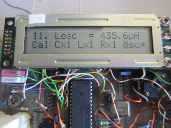
- Lx1 – inductor measurement from 1mH to ?? mH in 2 ranges
- Rx1 – resistor measurement from 100Ω to 99MΩ in 3 range
Component Meter2 Source file Meter2.asm
Component measurement using alternative LM311 relaxation oscillator and Colpitts oscillator. Based on measuring the time period of N cycles. This is slightly more accurate than above method as time of N= up to 1000 cycles is measured. It is more of a hardware solution and requires more construction.
- Cx2 – capacitor measurement from 10pF to 1000 μF in 5 ranges.
- Rx2 – resistor measurement from 100 ohm to 99M in 5 ranges.
- Lx2 – inductor measurement from 1mH to 60mH in 1 range.
- osc – inductor measurement (Colpitts method) from 70μH to 5000μH ? in 2 ranges.
Frequency Meter – source file Fmeter.asm
Containing functions that use PIC counters and timers, and little else;
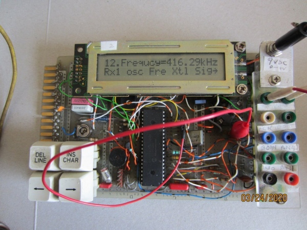
- FREQ – Frequency meter from 0Hz to 1000kHz in 3 ranges
- XTL – measures frequency of LP crystals (not tested)
- SIG – signal generator from 10Hz to 5KHz in 10 steps
- SMR – stepper motor – reverse direction
- SMF – stepper motor- forward direction.
Communications – Source file is comms.asm
Functions to transmit/receive signal to test serial and SPI peripherals;
- UTX test serial TX & inc and dec bit rate from 0.6 to 9.6k
- URX test serial RX & inc and dec bit rate from 0.6 to 9.6k
- SPM – tests SPI in master mode
- SPS – tests SPI in slave mode
FSK Radio Module – Source file is Radio.asm
Functions using RM01 and RM02 radio receive and transmit modules. These modules interface via SPI, which uses up most of Port C pins.
- RMB – set radio module BAUD rate
- RMF – set radio module RF frequency
- RMC – sets radio module clock frequency
- XLC – adjusts crystal capacitance load
- POW – sets transmitter power
- RM2 – transmit test data (RM02 module)
- RM1 – receive test data (RM01 module)
Control Module – Source file control.asm
- SV1 – Servo Output (using CCP1) from 1ms to 2ms in 0.1ms steps
- SV2 – Servo Output (using CCP2) from 1ms to 2ms in 0.1ms steps
- PW1 – PWM output (using CCP1) from 0 to 100% in 10% steps
- PW2 – PWM output (using CCP2) from 0 to 100% in 10% steps
Remote Data Acquisition – Source file is remote.asm
- Remote mode (Rem) – a set of commands so the meter can be operated from a computer via a serial interface. One command collects data logged in EEPROM over a period of hours. Another command reads voltages at full speed of the ADC into memory buffer, then transmit the buffer to PC, where the results can be displayed graphically. Effectively this is an oscilloscope, working over audio frequency range.
Time – Source file is time.asm
- Tim – just displays time in hh:mm:ss format and allows change using 4 buttons.
Step 3: Circuit Description
Circuit Description
3.1 Basic Development Board
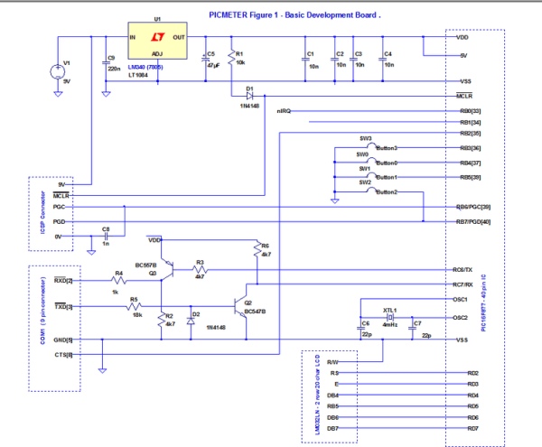
Figure 1 shows a basic development board to get PICBIOS running. It is very standard and straightforward, 5V regulated power source and decoupling capacitors, C1, C2 ….
The clock is 4 MHz crystal, so that TMR1 ticks in 1us intervals. The 22pF capacitors C6,C7 are recommended by Microchip, but do not seem to be actually necessary. The ICSP header (in-circuit-serial- programming) is used to initially program a blank PIC with the PICBIOS.
The serial port (COM1) – note TX and RX are swapped over, i.e. COM1- TX is connected to Port C-RX, and COM1- RX is connected to Port C-TX (commonly referred to as a “null modem”). Also the signal levels required for RS232 should really be +12V (space), and -12V (mark). However voltage levels of 5V (space) and 0V (mark) seem adequate for all PC’s I have used. So signal levels of RX and TX are just inverted by line driver (Q3) and line receiver(Q2).
The LM032LN (2-row 20-character) LCD uses the standard “HD44780 interface”. The software uses 4-bit nibble mode and write only, which uses 6 pins of port D. The software can be configured for nibble low (Port D bits 0-3) or nibble high (Port D bits 4-7) as used here.
The push button switches provide four inputs for menu selection. Use push to make switches as software detects the falling edge. The pull-up resistors (=25k) are internal to PORT B. Port RB6 cannot be used for switches, because of the 1nF cap (which is recommended for ICSP). There is no need for a reset switch ?
button0
menu options left [◄]
button1
menu options right [►]
button2
increment range/value/select [▲]
button3
decrement range/value/select [▼]
3.2 Analogue Inputs and Component Checker – Board 1
Figure 2 shows the analogue circuitry for PICMETER1. Analogue inputs AN0 and AN1 are used for general purpose voltage measurement. Select resistor values for attenuators to give 5V on input pins AN0/AN1.
For 10V input range, m = 1 + R1/R2 = 1 + 10k/10k = 2
For 20V input range, m = 1 + (R3+R22)/R4 = 1 + 30k/10k = 4
AN2 is used for temperature measurement using transistor Q1 as a “crude” temperature transducer. Temperature coefficient of NPN transistor at 20 celcuis = -Vbe/ (273+20) = – 0.626/293 = -2.1 mV/K. (see temperature measurement in Analog section). The LM431 (U1) provides a 2.5V voltage reference on AN3. Finally AN4 is used for or component testing in Analogue section.
For component measurement, the test component is connected across RE2 (D_OUT) and AN4 Input. Resistors R14 to R18 provide five different values of resistance used for resistance measurement (potentiometer method) in Analogue section. The resistors are “connected in circuit” by setting Port C/Port E pins as either Input or Output.
Meter1 performs component measurement by charging various combinations of known/unknown capacitor and resistor. LM311 (U2) is used to create CCP1 interrupts when a capacitor charges to the upper threshold (75% VDD) and discharges to lower threshold (25% VDD) These threshold voltages are set by R8, R9, R11 and potentiometer R10 which gives slight adjustment. When testing capacitors, capacitor C13 (=47pF) plus the stray capacitance of the board provide 100pF trim. This ensures that, when the test component is removed, the interval between CCP1 interrupts exceeds 100us, and does not overload the PIC. This trim value (100pF) is subtracted from component measurement by software. D3(1N4148) provides the discharge path when testing inductors and protects D_OUT, preventing voltage going negative.
λΩπμ
Step 4: Construction Guide
Construction Guide
A good thing is that this project is built and tested in stages. Plan your project. For these instructions I assume you are building PICMETER1, although the procedure is similar for PICMETER2 and 3.
4.1 Development Board PCB
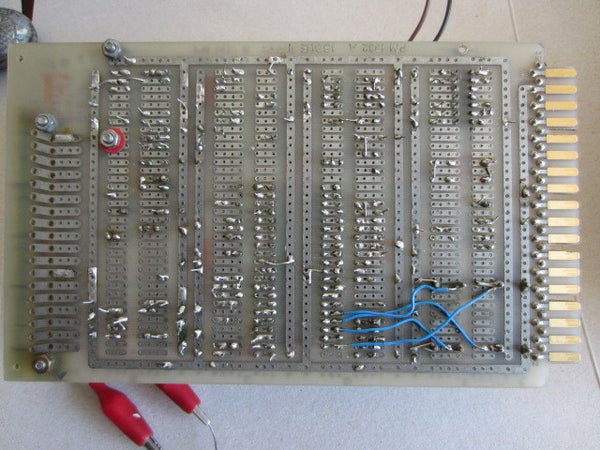
You need to build the basic development board (Figure 1) which should fit onto a 100 by 160mm standard size PCB, plan the layout to keep as tidy as possible. Clean your PCB and tin all copper, use reliable components and connectors, tested where possible. Use 40 pin socket for the PIC. Continuity check all soldered joints. It may be helpful to look at my board layout photos above.
You now have a blank PIC and you need to program PICBIOS into flash memory. If you have a programming method already – fine. If not I recommend the following method which I have used successfully.
4.2 AN589 Programmer
This is a little interface circuit that allows a PIC to be programming from a PC using the printer (LPT1) port. The design was originally published by Microchip in a Application Note. (reference 3). Get or make a AN589 compatible programmer. I have used an improved AN589 design described here. This is ICSP – meaning you insert the PIC into the 40 pin socket to program it. Then connect the printer cable to AN539 input and the ICSP cable from AN589 to development board. My programmer design takes its power from the development board via the ICSP cable.
4.3 PICPGM Settings
You now need some programming software to run on PC. PICPGM works with various programmers including AN589, and it is downloaded for free. (See References).
From the Hardware Menu, Select Programmer AN589, on LPT1
Device = PIC16F877 or 877A or autodetect.
Select Hex File : PICBIOS1.HEX
Select Erase PIC, then Program PIC, then Verify PIC. With some luck you get successful completion message.
Remove ICSP cable,
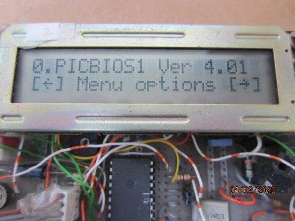
Restart the PIC, hopefully you see the PICBIOS display on the LCD, otherwise check your connections. Check the boot menu by pressing left and right buttons.
4.4 Serial Connection (Hyperterminal or Putty)
Now check the serial connection between PIC and PC. Connect the serial cable from PC COM1 to the development board and run a communication program, like the old Win-XP Hyper-Terminal, or PUTTY.
If using Hyperterminal, configure as follows. From the main menu, Call > Disconnect. Then File> Properties> Connect to tab. Select Com1, then click Configurebutton. Select 9600 bps, no parity, 8 bits , 1 stop. Hardware flow control”. Then Call > Call to connect.
If using PuTTY, Connection> Serial > Connect to COM1, and 9600 bps, no parity, 8 bits , 1 stop. Select “ RTS/CTS” . Then Session> Serial> Open
At the PICBIOS Boot menu, select “Command Mode”, then press [inc] or [dec]. The “PIC16F877>“ prompt message should appear on the screen (if not check your serial interface). Press ? to see list of commands.
4.5 Program PICMETER
Once the serial connection is working, programming flash memory is as simple as sending a hex file. Enter command “P” , which responds with “Send hex file…”.
Using hyper-terminal, from the Transfer menu > Send text file > PICMETER1.HEX >Open.
Progress is indicated by the “:.” as each line of hex-code is programmed. Finally Load Success.
If you are using PuTTY, you may need to use Notepad and copy/paste the whole contents of PICMETER1.HEX into PuTTY.
Similarly to verify, Enter Command “V”. In hyper-terminal, from the Transfer menu > Send text file > PICMETER1.HEX > OK.
Warning = xx…If you program a 16F877A chip, you will get some warning messages. This is to do with differences between 877 and 877A, which programs in 4 word blocks. Unfortunately the linker does not align the start of sections on 4 word boundaries. The simple solution is to have 3 NOP instructions at start of each section, so just ignore the warnings.
Restart and at the BIOS boot menu, select “Run application”. You should see PICMETER1 on the LCD .
4.6 Run PICMETER1
Now start building more sections of the development board (Figure 2) to get Voltmeter, Component Meter functions working as required.
Meter1 needs some calibration. On “Cal” function, adjust R10 to give readings of 80.00, 80.0nF, and 10.000uF approx. Then read a small 100pF on Cx1 function. If the reading is out, either change the trim cap C13 , or change the value of “trimc” in meter1.asm.
Now run PICBIOS Setup, and change a few calibration settings in EEPROM. Calibrate temperature by adjusting the 16-bit offset (high, low format). You may also need to change “delayt” value.
If your intention is to build the project as it is – Congratulations – you have finished ! Tell me about your success on Instructables.
4.7 MPLAB
But if you wish to make alterations, or develop the project further, you need to re-build the software using MPLAB. Download MPLAB from Microchip. This is the “old” one that is simple and straightforward to use. I have not tried the new labx development tool which looks far more complicated.
Details of how to create a new project, and then add files to the project in Full Documentation.
Step 5: Photos of Testing
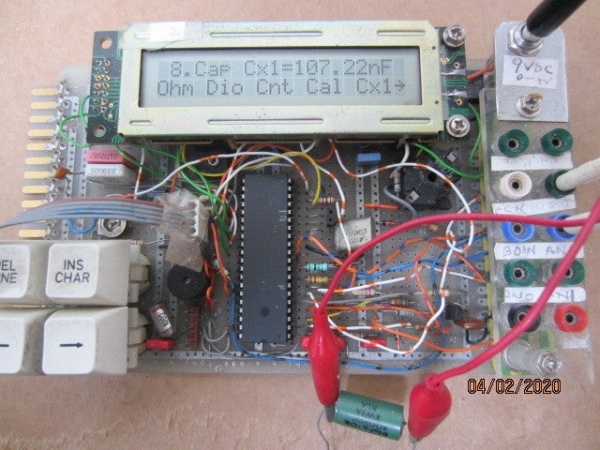
Photo above of thermometer, reading 15 degC
Testing frequency , reading = 416k
Testing inductor marked 440uF, reads 435u
Testing 100k resistor, reads 101k, that’s an easy one.
Testing of 1000pF capacitor, reading is 1.021nF
Step 6: References and Links
6.1 PIC16F87XA Data Sheet, Microchip Inc.
https://ww1.microchip.com/downloads/en/devicedoc/39582b.pdf
6.2 PIC16F87XA FLASH Memory Programming Specification, Microchip
http://ww1.microchip.com/downloads/en/devicedoc/39589b.pdf
6.3 Application Note AN589, Microchip Inc.
http://ww1.microchip.com/downloads/en/appnotes/00589a.pdf
6.4 PICPGM Download
http://picpgm.picprojects.net/
6.5 MPLab IDE v8.92 free download, Microchip
6.6 Data-sheets for Hope RFM01-433 and RFM02-433 modules, RF Solutions
https://www.rfsolutions.co.uk/radio-modules-c10/hope-rf-c238
6.7 LT Spice, Analog Devices
https://www.analog.com/en/design-center/design-tools-and-calculators/ltspice-simulator.html
6.8 A pic programmer circuit based on AN589, Best-Microcontroller-Projects
https://www.best-microcontroller-projects.com/pic-programmer-circuit.html
6.9 Open Source Files
Source: PIC16F877 Multimeter