On this page I hope to provide more details than I usually provide for those who wish to construct their own PIC-bot, realising that people actually try to make this stuff. Traditionally, my ‘bot pages are for documenting the essentials, not in the kind of detail needed to make as if it were a kit. I document my projects bugs and all, but the simple PIC-bot needed to be worked out. The original 5x platform was too complicated and required too much equipment to translate into how-to steps, this new PIC-bot is much easier to contruct, program and document. I’m loving it already. No more UV!
I don’t expect any awards for the efficiency of my “solar engine”, but as a microprocessor-based device the PIC-bot is very efficient. The 0.5 farads of capacitance is enough to move many dozens of times with a full charge and still have enough power to maintain cpu operation overnight. With a 100 watt bulb about a foot away it can gather enough power to begin moving in about 15 minutes from a full discharge. Because it’s coded to gather power then move many times it appears much more active than the typical solar-powered robot, of course it must rest longer between popping cycles. When it gets enough power it doesn’t come alive right away, rather it waits for something to change in the environment or some time to pass so that when it does wake up it puts on a show. Weight is just over an ounce.
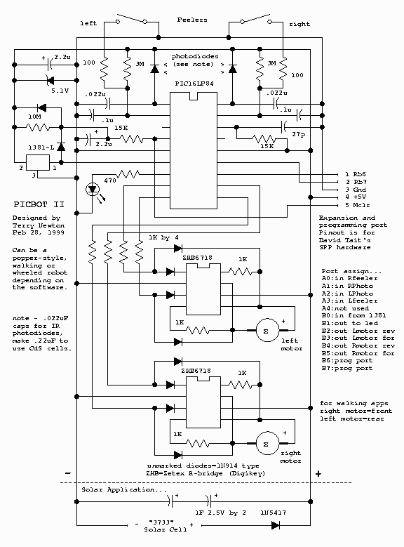
 The in-circuit programming port was designed for David Tait’s SPP programming hardware and software [the original site is gone, navigate to the “In-circuit 16F84 Programmers” page]. I modified the posted circuits to supply a current-limited +5 volts to the robot while programming. The SPP programmer is picky about the parallel port, probably because no buffering is used. It wouldn’t run from my cheap printer card but works fine connected to the motherboard’s built-in printer port. The programming port is entirely optional, any PIC programmer can be used.
Robot Software…
Here’s the latest version of the PIC-bot II software in Parallax format. Rename to “*.src”.
Here is a link to a hex dump of version 1.20 after experience, assembly not required. Rename to “*.hex”.
To assemble my code you’ll need the Parallax or TechTools assembler. The SPP programmer reads .OBJ files directly but beware not all programmers do. I prefer the Parallax format, I was afraid I would have to actually learn the Microchip instructions and even rigged up disassemblers and batch files in case I had to convert to .ASM and .HEX files. Thankfully SPP makes that unnecessary.
The modern PIC16LF84 chip allows the robot to be programmed in other languages besides assembly – C and other compilers are available free for download.
Construction…
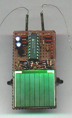
I made my prototype LF84 popper on a piece of perfboard 2.7 by 1.5 inches with the 3733 solar cell occupying half of it. Unless you’re really good at miniature construction techniques go bigger or make the solar cell separate from the controller board to help space it out. To make it fit, I had to use free-form technique to make the H-bridge assemblies then mounted them as components. For effective popping, the robot must be balanced. The LED is the front skid but you don’t want all the weight on it. When it fires, it should lift the LED off the ground. A wire prevents the robot from tipping back too far. The touch sensors can be made by coiling up guitar string into a spring and suspending a wire inside, for mine I temporarily borrowed the touch feelers from my photopopper.
The Zetex H-bridges are surface-mount parts, fortunately they’re larger than typical smd parts so it isn’t too hard to solder wires and parts to them. If new to free-forming practice on other tiny stuff first, it takes a bit of practice. It would be really cool if I had a PC board with lands for the bridge chips, on my wish list.
A more reasonable and compact layout would have been to spread out the H-bridge components and elevate the solar cell on top of the bridges, maybe next time. Use your imagination, layout is not critical but try to make it as light as possible and don’t forget about balance.
June 26, 1999 – I got into a mad scientist mood last night, and produced a tiny PicBot II using a few parts “borrowed” from my original 5x picbot. It uses Tiny Pager Motors from Solarbotics, and weighs about 5/8 of an ounce. The circuit is mostly like the posted circuit except that it does not have protected bridges (too lazy to add the diodes), no LED (got the other one to debug with) and uses 470 ohm resistors between the PIC and bridge input diodes (had tiny 470’s but no tiny 1K’s). Oh yea, omitted the extra 2.2uF rail cap and 5.1V safety zener. Works great! Now to arrange some sort of protective shell around both of them to keep ’em from shorting each other out, probably doesn’t hurt anything but still…
 Parts List…
Parts for the robot… (DK# = Digikey number)
1 – PIC16LF84-04/P PIC processor – DK# PIC16LF84-04/P
1 – 18 pin IC socket – DK# A9318
2 – Zetex H-bridge chips – DK# ZHB6718CT
1 – 1381-L voltage trigger – DK# MN1381-L
10 – 1N914 or 1N4148 diodes – DK #1N4148MSCT
1 – 5.1 volt zener diode – DK# 1N5231BMSCT
1 – Schottky diode – DK# 1N5817CT
2 – 1 farad 2.5 volt AL-Gold capacitors – DK# P6963
2 – 2.2uF capacitors – DK# P6261
2 – 0.1uF capacitors – DK# P4525 (min 10)
2 – 0.022uF capacitors – DK# P4517 (min 10)
1 – 27pF capacitor – DK# P4017A or 1306PH (min 10)
2 – 100 ohm 1/8 watt resistors – DK# 100EBK (min 5 on resistors)
1 – 470 ohm 1/8 watt resistor – DK# 470EBK
8 – 1K 1/8 watt resistors – DK# 1.0KEBK
2 – 15K 1/8 watt resistors – DK# 15KEBK
2 – 3 meg 1/8 watt resistors – DK# 3.0MEBK
1 – 10 meg 1/8 watt resistor – DK# 10MEBK
1 – red high-efficiency jumbo LED – DK# 160-1127
1 – 5 pin header for programming port – DK# WM4003
2 – pager motors – Solarbotics
1 – “3733” solar cell – Solarbotics
2 – IR photodiodes – Solarbotics
2 – spring-type feeler switches (can make with a thin guitar string)
… heatshrink, perfboard, and other common stuff
For more detail: PIC-Bot II