Introduction
This project will describe how to make a simple digital voltmeter (DVM) using a PIC16F688 microcontroller. The range of this DVM is 0-20V, but you can easily increase or decrease the range of input voltage as your requirements after you understand the voltage scaling method described in this project. The PIC micro reads the input voltage through one of the 8 analog channels and convert it to a 10-bit digital number using the internal ADC. Doing some math with ADC conversion (you will see later), this number can be converted to the actual measured voltage. The voltage is displayed in an HD44780-based character LCD.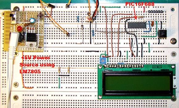
Circuit Diagram and Description
You cannot feed a 20V signal directly to a PIC microcontroller’s input channel. It is too higher than its operating voltage, and the microcontroller could be damaged. So, first we need a voltage scaler that will scale down the input voltage to the safe operating voltage range of PIC16F688.
resistors, R1 and R2, the input voltage ranging from 0-20V can be down converted to 0-5V. For the chosen values of R1 and R2, you can see that the output (Va) from the resistor divider network is 1/4th of the input voltage. If the input voltage goes beyond 20V, Va will exceed 5V, and this could be harmful for the PIC microcontroller. If you connect a 5.1V Zener diode across the R1 resistor, the output voltage Va will never exceed 5.1V. This will protect the microcontroller from any possible damage due to high voltage input. The voltage Va will go to AN2 (pin 11) channel of the PIC16F688 microcontroller. The rest of the circuit is shown below.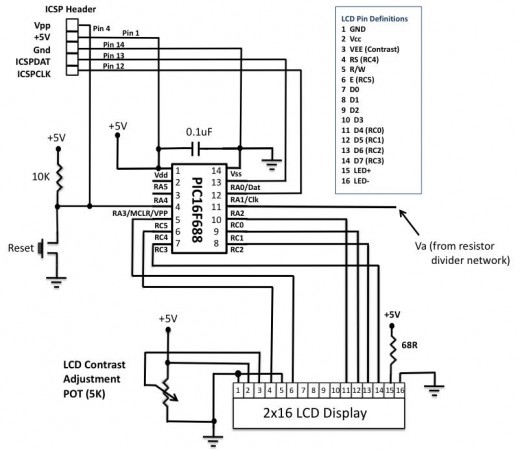
The LCD display is connected in 4-bit mode. If you have just 14 pins in your LCD module, then you may not have a back-light facility and you can ignore the pins 15 and 16. The contrast adjustment is done through a 5K potentiometer connected between +5V and Gnd. An in-circuit serial programming (ICSP) header is provided so that you can easily upgrade the firmware inside the PIC microcontroller in future if you make any changes. An external reset is helpful to bring the entire system to a known initial condition, when the microcontroller stops executing the program for some reason.
For more detail: PIC-based Digital Voltmeter (DVM)