I promised to post some of my past microcontroller vision projects. This one has a Microchip PIC directly sampling a video signal. 8 pins well used.
Collapsible Quadruped Robot with Computer Vision, Laser Ranging, and Servo Control on a Single-Wire Network
Photos and video capture by Glenn Currie.
Download project design_files_PicVid97.zip.
Austin Texas, 1997. I found a nice piece of aluminum and the Microchip PIC12C672 had just come out so I built this robot with basic machine vision, servo control, single-wire network, wireless com, and laser ranging – all based on the 8-pin microcontroller.
The goal was to develop the robot control software on the PC and then add a main processor to the robot after robot motion etc. was worked out.
The collapsible design worked; the robot would collapse and expand. (It was more like a jump since the servos were so strong.) The ranging and video motion targeting worked but only caught motion within a window of speeds–a smaller window than typical methods. Instead of developing a walking algorithm, I focused on computer vision. Later, following the same physical design, I designed a credit-card sized collapsible quadruped with micro-servos mounted to a cell phone battery. Again the computer vision issues became more important to solve. Robots can walk, it’s time for them to see.
Until microcontrollers are available with a pixel-processing peripheral, “I do not consort with those of the robot race.”
 Main ideas:
- Modular design, add servos and other functions as needed.
- Camera output is sampled directly by the PIC.
- Single wire communications and control network.
- The PIC detects object motion by sampling pixels from the video images.
- Servo final positions are controlled by the PC during hosted development.
- The servo position pulses are generated at the PIC inside each servo.
- Laser ranging for direct distance measurement, size, 3D.
- Power measurement at each servo PIC for servo loading and actual position feedback.
- Wireless data link to a PC serial port for telemetry and hosted development.
- Wireless composite video link for monitoring the camera and machine vision functions.
- PC receives locations of objects detected by the video camera.
- Video sampled at 30fps.
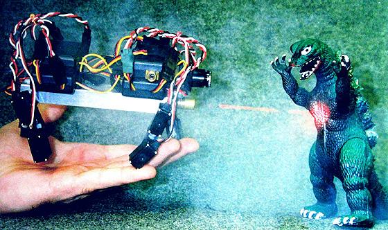
Laser ranging by a laser offset from the camera axis. The top image shows the laser spot detected higher up in the image (further away). The lower image shows the laser spot detected lower (closer to the camera).
The PIC scans the incoming video and compares values between frames to detect changing pixel values. The vertical cursor pattern is drawn on the video signal by the PIC for demonstration. The cursor marks widen when changing pixel values are encountered. Laser ranging is accomplished by flashing the laser during every other frame. The flashing laser spot is detected as an area of changing pixel values.
Servo with PIC installed. A servo with a clear body was used for the first tests.
The PIC receives commands from the 1-wire network, converts position command to pulse sequence, sends pulses to the servo, reads voltage across a resistor for a current measurement (servo loading), reports servo position and power to the 1-wire network.
(Write-up I entered in the Circuit Cellar Design Contest 1997)
Distributed Pics: Networked Embedded Video Acquisition and Servo Control for a Quadraped Robot
Microchip Pic12C672 microcontrollers are used in a walking robot control system that has several servos and a video camera controlled by a remote PC. The design goal for the hardware was a system that had individually addressable servos and camera on a communications network with a wireless link to the PC.
Requirements for the overall design centered on simplicity and utility. Servos should be easily added and removed without having to change microcontrollers or support circuitry, accuracy for servo power measurement to indicate loading should be better than 10% of full scale, accuracy for servo position sensing should be better than 5% of full scale, and accuracy for video ranging should be better than two inches at one foot. Video motion detection should function reliably even with a complex video scene. The prototype should demonstrate basic functions and take commands from a common RS232 ASCII communications program found on any PC. A separate user interface for more complicated robot control will be written for the PC after the prototype is proven.
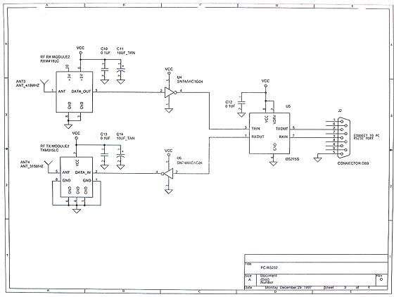
The implementation was to embed a Pic12C672 in each servo (ServoPic) and in the camera (VideoPic). Each ServoPic measures servo load, reports servo position and receives a list of movements so that the robot can walk without further updates from the PC. The VideoPic reports the location of moving objects in the video scene, reports ranging data, and acquires video pictures. Each Pic microcontroller uses a single pin to transmit and receive the RS232 data. The communications backbone is an RS232 (protocol, not voltage level) network attached to the ServoPics and the VideoPic. The network communicates with a remote PC via a wireless Linx receiver and transmitter pair at each end.
Contents
I. Overview
II. VideoPic: Video Acquisition, Motion Detection, Ranging, and Single Wire Communication
III. ServoPic: Servo Control, Position Monitor, Power Measurement and Single Wire Communication
IV. Controller Network
V. The Prototype
VI. Photos, Demonstration
VII. Schematics, Source Code, Parts List
I. Overview
Distributed Pics: Networked Embedded Video Acquisition and Servo Control for a Quadraped Robot
Microchip Pic12C672 microcontrollers are used in a walking robot control system that has several servos and a video camera controlled by a remote PC. The design goal for the hardware was a system that had individually addressable servos and camera on a communications network with a wireless link to the PC.
Requirements for the overall design centered on simplicity and utility. Servos should be easily added and removed without having to change microcontrollers or support circuitry, accuracy for servo power measurement to indicate loading should be better than 10% of full scale, accuracy for servo position sensing should be better than 5% of full scale, and accuracy for video ranging should be better than two inches at one foot. Video motion detection should function reliably even with a complex video scene. The prototype should demonstrate basic functions and take commands from a common RS232 ASCII communications program found on any PC. A separate user interface for more complicated robot control will be written for the PC after the prototype is proven.
The implementation was to embed a Pic12C672 in each servo (ServoPic) and in the camera (VideoPic). Each ServoPic measures servo load, reports servo position and receives a list of movements so that the robot can walk without further updates from the PC. The VideoPic reports the location of moving objects in the video scene, reports ranging data, and acquires video pictures. Each Pic microcontroller uses a single pin to transmit and receive the RS232 data. The communications backbone is an RS232 (protocol, not voltage level) network attached to the ServoPics and the VideoPic. The network communicates with a remote PC via a wireless Linx receiver and transmitter pair at each end.
A quadraped robot was constructed. Each leg consists of two sub-micro servos, connected in a way that allows dog like walking and sitting. A ninth servo, controlled by a tilt sensor, will later serve as a tail to balance the robot during the four legged gait. The video camera is mounted to the front of the body. The advantages of this arrangement are that the camera can be tilted up or down by changing the body tilt and the forelegs can be used as arms when the body weight is placed fully on the hind legs. The body is a five inches long, 3/4 inch wide aluminum channel. The robot is 3.5 inches tall standing, and 1.75 inches collapsed. The robot is designed to function from a single 3.6 V to 4.8 V battery pack. The battery is mounted up under the body, inside the aluminum channel.
This document describes the design of the sensing, control and communication circuitry of the prototype, excluding the tilt sensor and tail.
II. VideoPic: Video Acquisition, Motion Detection, Ranging, and Single Wire Communication
VideoPic
The Pic12C672 eight pin microcontroller has exactly the peripherals and pins required for remote video acquisition and control. Pin usage is 1. power, 2. ground, 3. live video input, 4. clock input, 5. video sync input, 6. video marker output, 7. communications input/output, and 8. laser ranging enable output or clock output.
Video Camera
Marshall Optical Systems Division supplied the V-X0071 CMOS video camera with a 3.6 mm lens.
Besides the composite video signal, two other signals are required from the camera for the VideoPic. These are a pixel clock and vertical sync. The V-X0071 provides these signals, unfortunately the pixel clock is disabled during the vertical sync signal. The simplest work around is to tap into the video camera crystal oscillator clock. If the camera did not provide vertical sync and pixel clock, a video sync separator and PLL circuit would need to be added to the VideoPic circuit.
Modifications to the camera are shown on the related schematic. A single inverter gate was connected to the video clock as a buffer. The inverter package is very small and can be glued to the back of the camera. The linear voltage regulator was removed from the camera board so that the camera could be powered from the common VCC.
Video Display
For monitoring live video during development, a video cable is attached from the RCA connector of the VideoPic circuit to a video monitor. A Maxim video buffer drives the cable and inserts markers generated by the Pic. The markers appear on the monitor as short horizontal lines with a gap in the middle to indicate the exact location of each video sample. When movement is detected the mark for the corresponding location widens. Sensitivity and resolution were tested by observing live video as well as serial data.
Motion Detection
Live video (DC coupled, 1 V min. to 2.5 V max.) was connected directly to the analog input of the Pic12C672. The video signal is sampled by the Pic A-D converter and compared to previous samples to detect change in the scene indicating movement. The detection threshold is adjustable for more or less sensitivity.
Two scan modes are implemented:
1) 64 sample locations are spread out over the screen. Markers are added to the video as shown. The small space between each pair of markers is the exact location of the sample. Any change in the video scene that enters the sample space will be detected as movement.
The first acquisition at each location is saved. All samples after that are compared to the first samples. Any movement, even if it is very slow, causes detection. Again the locations are sampled and saved, and then observed indefinitely for the next movement.
Movement reports are two bytes indicating the first horizontal and vertical location of a pair of columns, and two bytes indicating which samples detected movement by which bits are set in the bytes (MSB is the top marker). For example, if the third column is at video line 0×10 and 0×20 clock cycles ((0×20 * 4) video clock cycles) horizontally, and movement is detected at sample five, third column, and sample seven, fourth column, the VideoPic would report V: 0×10, H: 0×20 0×08, 0×02
 The VideoPic causes the markers at locations of detected movement to widen.
2) 64 locations in a vertical column are sampled every other frame, and then compared on the frames in between. Response time is 33 mSec., but slow moving objects will be missed. The column can be scanned smoothly across the screen looking for moving objects. Scanning is also useful for tracking the laser spot when ranging. The laser will not always be alligned perfectly with the center axis of the lens. To prevent having to make adjustments by hand, the detection column scans when it loses the laser spot and stops while the laser is detected.
Movement reports are two bytes indicating the first horizontal and vertical location, and eight bytes indicating which samples detected movement by which bits are set in the bytes (MSB is the top marker).
The VideoPic causes the markers at locations of detected movement to widen.
64 total sample locations
Several of the motion detection parameters are adjustable from the remote PC, including sensitivity threshold, sample location, horizontal scan speed, scan mode, and distance between samples. The Pic can send A-D data to the PC for video capture. The Pic can cause the PC to sound a beep each time movement is detected, and send immediate locations of movement.
Laser Ranging
The laser is mounted directly above or below the camera and aimed at an angle towards the center of the video camera lens axis (center of the video picture). The closer an object is to the camera, the further from the center the laser spot appears in the picture.
The laser is enabled for one frame and disabled for one frame repeatedly to cause a detection in scan mode 2) above. The stack of 64 sample locations gives a good vertical resolution of the laser spot location.
A 635nm laser module (Resources Un-Limited) modified to operate from 3-6V supply (Jameco Laser Driver #126711) was found to be very bright. The camera even detected the spot on non-reflective black fabric. A bright white wall was a problem, helped some by a Kodak Wratten 80A IR block filter. Rather than go into the details of modifying the laser, I recommend finding a laser module that already operates from 3-5V.
If the VideoPic was used in a security application instead of robotics, an alternate function for the laser enable pin could be to activate an alarm or the record function of an attached VCR when motion is detected in the video scene. The Pic could simply throw a relay or modulate an IR emmitter pointed the VCR remote control input.
For more detail: Microchip – Let my robot see!