Design Goals
DIY Friendly – Something that the Make audience could easily build
Improve the reference design – Better measurement resolution, better timing, lower power, non-stop logging
Minimal parts count – Lower cost and shorter build time
Powered by a single 1.5 volt cell (AA, AAA, N or similar) and optional supplementary solar power

Parts Selection
One of the design goals is to use the fewest parts need to accomplish the other goals. The reference design uses an EEPROM to store the logged data. The 24AA1025 is a rather expensive part for 128 k bytes of storage. Using a microcontroller with a large internal writeable non-volatile memory may allow this part to be eliminated. That would reduce parts cost and build time. The Microchip parametric parts selector was used to display 8 bit PIC microcontrollers in a 28 pin or smaller package. The displayed list of parts was then sorted by memory size. The highest capacity flash memory shown was 128 k bytes. That is the same capacity as the EEPROM, but some space will be taken by the firmware. The PIC18F27J53 look like a good choice. It is available in a DIP package so the logger can be easily built on solderless breadboard. It also features a real time clock (RTC) that will allow time stamps and a precise sample rate. The analog to digital converter (ADC) is 12 bits – an improvement over the 10 bits of the reference design. It also has USB that could be used to eliminate the need for the FTDI USB to serial cable. The price is 3.23 USD/qty100. The reference design used a PIC at 2.05 USB/qty100 and the 24AA1025 at 2.85/qty100 for a total of 4.90 USD. Cost savings are 1.67 USD. If this where a commercial product, there would be additional cost savings by using a smaller PCB, reduces assembly time and potentially greater reliability (fewer parts to fail.) One possible problem with using the microcontroller’s flash memory for data storage is the write cycle limit. Flash memory can be read constantly, but degrades when it is written. The number of write cycles for the PIC18F..J series parts is 10,000. EEPROMs usually allow 1,000,000 or more write cycles. If one sample is logged every second, it will take about 28 hours to fill 100 k bytes. 10,000 cycles would take more than 30 years, so this is not a problem.
The MCP9700 used in the reference design is a low cost temperature sensor will adequate accuracy. No reason to use a different part.
Storing data in flash memory
The reference design writes each reading to the EEPROM at the time it is read. The EEPROM allows this, but it has to read and write an entire 128 byte page just to update 1 byte. Power consumption could be reduced by buffering 128 bytes to RAM and writing whole pages to the EEPROM.
Flash memory is not as “smart” as EEPROM. It requires that memory written must first be explicitly erased. The flash memory is erased in chunks of 1 k bytes. Writing to flash is done in chunks of 64 bytes. It is not possible to write just one byte. To keep the code simple both erasing and writing will be done in chunks of 1 k bytes. 1000 readings will be accumulated in RAM. After the 1000th reading, they will all be written to flash along with up to 24 bytes of metadata. The metadata includes the real time stamp of the first reading and the absolute value of the first reading.
102 k bytes of flash are needed to store 100,000 readings. 100 k bytes will contain logged data. 1 k bytes will always be erased – this separates the head and tail of the circular buffer. The highest 1 k of flash is not used because the top 8 bytes contain the config words. It is easier to just ignore this last 1 k than to make exceptions for it. The total flash size is 128 k, so 26 k is available for the firmware.
When highest block of flash has been used, the buffer will wrap around back to the first block. The flash will always contain the latest 100,000 readings.
The next block to be used will be erased before the current block is written with the data collected in RAM. This ensures that there will always be an erased block between the head and tail of the circular buffer. If the erase fails, then the previously erased block will remain.
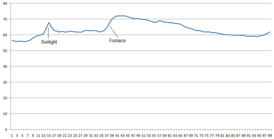
The plot below is the first dataset from the logger. Excel can not handle 100,000 rows, so only the first reading of each block of 1000 is plotted.
Data transfer
The Ymodem protocol is used to reliably transfer the logged data in binary form. This protocol is quite old and still well supported. It uses a 16 bit CRC to detect transmission errors and can handle text or binary data. Downloading the logged data is simply a matter of using terminal software to initiate a Ymodem download. A 101 k byte file named ‘datalog.bin’ will be downloaded in about 1 minute. The entire 101 k is transferred even if only part of it contains logged data. Logging does not stop during download.
Preventing data resolution loss
The reference design converts the ADC reading to degrees C and stores that in the EEPROM. This results in a loss of resolution. A temperature of 23.4 will be stored as 23 – an unnecessary error of 0.4. If a steady slow change in temperature where plotted, it would be jagged line rather than a smooth line. Storing the actual ADC reading will preserve the full resolution of the measurement. It can be converted to whatever unit of measure is desired with whatever resolution is needed. Using the logger for something other than temperature would not require any firmware changes. Storing all 10 or 12 bits from the ADC would require more space than storing the scaled value as an integer. If the ADC reading changes by a small amount from one reading to the next, then the change in value can be stored rather than the absolute value. Eight bits will allow changes of -128 to +127 between each reading. The code is written to propagate any overflow error to the next reading. For example a change of +200 would be encoded as +127 and the error of +73 would be added to the next sample. This may result in an occasional incorrect reading, but the sequence will correct itself. It is effectively a low pass filter.
For more detail: Low power temperature data logger using PIC18F27J53