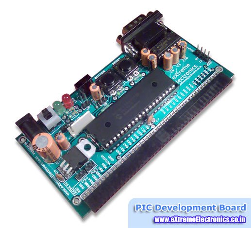
RS232 can be used to communicate between a variety of devices. Like your MCU and a GSM module or a PC. In this tutorial we will demonstrate a link between a PIC18F4520 MCU and a standard PC. On PC we will run a terminal program like RealTerm or Hyperterminal.
Connecting PIC18F4520 with a PC
In Serial Communication the line that is used to transmit data is called Tx and the line used to receive data is called Rx. The PIC MCU uses TTL level for logic that is a 1 is a 5v and 0 is 0v but RS232 standard uses different scheme for logic level, so we need a level converter in between.
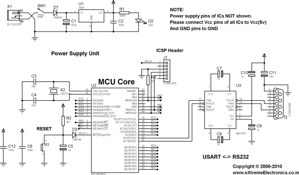
Schematic for Testing Serial Communication with PIC18F4520
The above image show the schematic of circuit you will need to make. Most of the circuit is common for many other application too. The only specific part is the level converter which built around the MAX232 IC.
The heart of this unit is PIC18F4520 chip (you may also use PIC18F4550). The ICSP connector is used to download programs via a PIC programmer. RESET switch is used to reset the MCU so its start executing from the beginning of the program. A 20MHz crystal is the source of oscillation. C12 and C6 which are 0.1uF (Marking 104) should be placed as closed to the MCU as possible, they provide extra immunity to noise.
For more detail: RS232 Communication using PIC18F4520’s USART – PIC Microcontroller Tutorial


