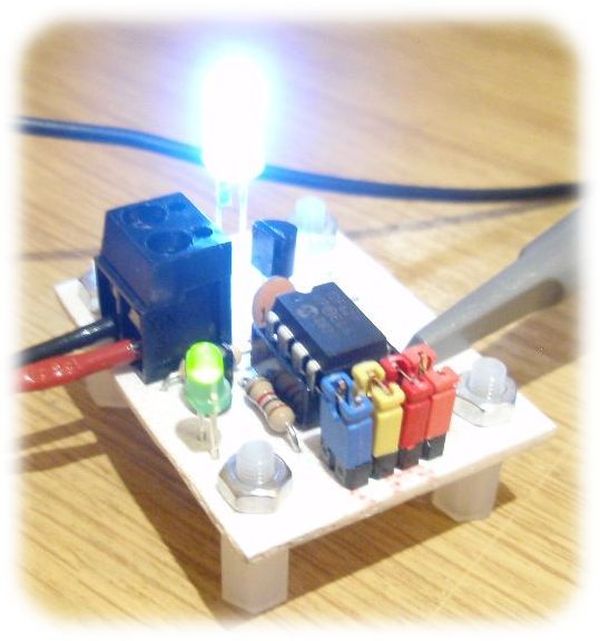
Description
This project functions as a simple strobe for driving an LED. The use of an output transistor allows it to pulse the strobe LED with a current up to 100mA.
Four jumpers provide options for changing the pulse width, strobe repeat interval and single or double strobe flash. The programmer ready code has default timings which are easily customised by editing values in the PIC’s EEPROM at programming time.
This is one of those applications where it’s arguably better than a 555 timer based solution but in practice you could build it with a 555 timer faster than you can write the PIC code. However it only needs the code writing once, I’ve done that and designed a small PCB too so away you go.
Circuit Description
The circuit provides a LED strobe function with jumper selectable operating modes.
The strobe interval can be configured using 4 jumpers for 1,2,3 or 4 seconds; strobe on time of 30mS or 100mS and single or double strobe pulse.
Since the PIC can only supply 25mA from its I/O pin a transistor is used to increase the maximum current driven through the LED. This transistor has a maximum collector current of 100mA which is adequate for driving most types of 5mm LEDs. The PIC could be used to control a higher powered output switch if desired.
The value of R3 series current limiting resistor for the strobe LED has been selected on the conservative side rather than providing maximum brightness. With a 5 volt supply and LED with 1.8V forward voltage yields current of approximately 47mA.
The strobe LED can either be installed on the PCB in position LED1 or off-board via connector CN2. If the off-board option is used do not install a LED into position LED1 on the PCB.
LED2 is a monitor LED, if the off-board strobe LED is used, this LED can be useful for monitoring the operation of the circuit. If you don’t want this option, just omit LED2 and R4.
Capacitor C1 is used to decouple the 5 volt power supply rail. If you are building the circuit on a breadboard or stripboard you should ensure it is located close to the PICs Vdd connection (pin 1).
The input voltage must not exceed 5 volts. It can run from as low as 3 volts but you will need to modify the Strobe LED resistor value. Also be aware of the LED forward voltage; some high brightness LEDs and in particular white LEDs and some blue and green LEDs have forward voltages in excess of 3 volts.
The operating modes are selected by using jumper block JP1. If you are building the strobe for a specific application you may want to hardwire inputs to ground as required rather than fit the jumper pin header.
Choosing R3 / LED1
Obviously we want the strobe LED to be as bright as possible. It is important that the series resistor R3 is chosen so that the LED current does not exceed the manufacturers rating. Since different LEDs have different maximum forward current and voltage ratings you must select this resistor to suit the specific LED you are using.
For other LEDs you can use this site to calculate the resistor needed http://led.linear1.org/1led.wiz When you go to this site it asks for the source voltage. This will be 5 volts, or if you’ve used batteries to power the strobe, the total battery voltage. Also note that driver transistor Q1 is only rated to 100mA so do not exceed this even if the LEDs used can.
Strobe Operating Modes
The section refers to the default timings used in the programmer ready firmware download.
The pulse width, interval and strobe mode are user selectable using the JP1 jumper block. There are two strobe modes, single and double pulse. The double mode has a (default) 175mS off-time between the two pulses. As shown in the diagram below, the interval is measured from the end of one pulse group to the start of the next group.
For more detail: LED Strobe for PIC12F629

