I hope that you already go through the first tutorial of MPLAB XC8, Getting Started with MPLAB XC8 – LED Blinking. In that tutorial we learn how to use an output pin by driving an LED. In this we will learn how to read an Input pin using a push button switch. We already seen that TRIS register is used to set direction of each IO pin, ie Input or Output and PORT register is used to read or write status of an IO pin. 1 at TRIS bit makes the corresponding pin Input while 0 at TRIS bit makes the corresponding pin Output.

An Input pin will be in Hi-Impedance state.Writing 1 to PORT bit corresponding to an Output pin makes the pin Logic High (VDD) while writing 0 to PORT bit makes the corresponding Output pin Logic Low (VDD). PORT register can be used to read physical state (actual voltage level) of an input pin. If an Input pin is at a potential near to VDD, reading PORT bit will give 1 and if the input pin is at a potential near to VSS, reading PORT bit will give 0.
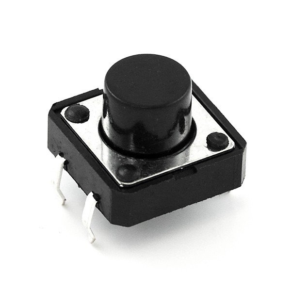
In this tutorial a push button switch is connected to a pin declared as input (TRIS bit 1) and an LED is connected to a pin declared as output (TRIS bit 0). When the switch is pressed, the LED will glow for 3 seconds.
Circuit Diagram

VDD and VSS of PIC Microcontroller is connected to +5V and GND respectively to provide the necessary power for the operation of microcontroller. 8MHz crystal is used to provide necessary clock for the operation of microcontroller. Pin RD0 (PIN 19) is declared as an input pin (TRIS bit 1) to which push button switch is connected. Pin RB0 (PIN 33) is declared as an output pin (TRIS bit 0) to which LED is connected. A 10KΩ PULL UP resistor is used along with push button switch to ensure that RD0 is at Logic High (VDD) when the switch is not pressed. Whenever the switch is pressed, RD0 becomes Logic Low (VSS). A 470Ω resistor is used to limit the current through the LED.
For more detail: Using Push Button Switch – MPLAB XC8
