An IR sensor is an electronic device, that produces in order to detect some parts of the environs. An infrared sensor can measure the heat of an object as well as detects the motion. These sensors are used to measure only IR radiation, rather than producing it that is called as a passive infrared sensor. Generally in the IR spectrum, all the surrounding objects generate different form of thermal radiation.These kinds of radiations are not observable to our eyes, that can be sensed by an IR sensor. The emitter of the sensor is infrared LED and the sensor is an IR photodiode which is sensitive to infrared light of the same wavelength as that produced by the infrared LED.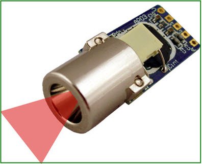 When infrared light drops on the photodiode, the resistances and o/p voltages change in proportion to the received magnitude of the infrared light.
What is Infrared Sensor?
IR sensor is an electronic device which is used to sense heat & objects. It works with the sensing of IR radiations and variation in heat in its nearby. IR sensors are classified into two types such as photo IR sensor and thermal IR sensor.
- A thermal infrared sensor detects the change of heat from its nearby objects
- The photo IR sensor uses a photo diode to sense IR radiations. In this article as an infrared sensor a photo IR sensor is used to build the circuit.
The applications of the infrared sensors involve from domestic devices to industrial devices. These sensors are used in object sensing, motion detectors, obstacle avoidance robot, gas leakage detection, smoke detection, measurement of distance, robotics and many more.
Infrared Sensor Circuit with Working
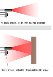
The IR sensor circuit diagram is shown below. In the circuit below, the main parts of this sensor are photo diode and the IR receiver LED. Photo diode emits IR radiations when it strikes to any object, then turn back with some angle. The IR receiver detects reflected radiations. Because in this circuit, we are using a photo diode, so this type of sensor is called a photo infrared sensor.
The Required Components of Photo Infrared Sensor include IR receiver TSFF5210, Photodiode, 100 ohm resistor, 10k resistor, 10k variable resistor and LM358 IC. IC Lm358 is used as a comparator when IR receiver senses IR radiations. When the o/p of lm358 goes high, then LED connected at the o/p turns ON. The output pin of the IC LM358 is used to interface with PIC microcontroller.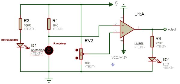
IR Sensor Circuit Interfacing with PIC18F4550 Microcontroller
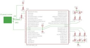
The output of the infrared sensor circuit is connected to PIC microcontroller pins and the microcontroller will take it as digital input either 0 or 1. According to the o/p of the infrared sensor module, the microcontroller will react by glowing LED.
The o/p of the infrared sensor circuit is connected to RA0 pin of the pic microcontroller. It is arranged as i/p with TRISB registers and the o/p of this interfacing will be displayed on LED that is connected across PORTD includes RD5, D6, RD7. Here o/p pins are RB0 and RB1.
This project doesn’t need to perform any ADC, hence we are going to turn off the ADC and all the pins configured as digital. At the 1MHz default oscillator frequency, sometimes the o/p gives unbalanced result. Therefore, tuning the PIC microcontroller to 8MHz solves the problem. From this we can conclude that, this microcontroller works with 1MHz and we can change the settings of OSCCON bits to adjust the oscillator frequency according to your necessity.
OSCCON register bits can be found in the microcontroller datasheet with description. A bits settings table to configure the PIC microcontroller oscillator frequency, internal oscillator is configured with 8MHz to avoid rebouncing of the switch. In the above circuit, we can use voltage regulator IC 7805 to avid voltage variations which could damage the pic microcontroller. Make sure that the input of the microcontroller should not exceed +5Volts.
Coding for IR Sensor Interfacing with Microcontroller
/*
* File: infraredinput.c
* Author: ron
* December 10, 2012, 1:21 PM
*/
#include <p18f4550.h> // Include Header for PIC18F4550
#define switch1 PORTAbits.RA0 // Switch on RA0
#define led1 LATDbits.LATD7 // led1
#define led2 LATDbits.LATD6 // led2
#define led3 LATBbits.LATB0 // led3
#define led4 LATBbits.LATB1 // led4
#define led5 LATBbits.LATB2 // led5
void main (void)
{
/* If you want your microcontroller to work at 1MHZ then comment the three lines below */
OSCCONbits.IRCF0 = 1 ; // set internal clock to 8 MHz
OSCCONbits.IRCF1 = 1; // For Avoiding switch debouncing problem
OSCCONbits.IRCF2= 1; //
/* Input output settings*/
TRISAbits.TRISA0 = 1; // RA0 Input for taking input from IR sensor
TRISDbits.TRISD7 = 0; // Port D pins output
TRISDbits.TRISD6 = 0;
TRISBbits.TRISB0 = 0; // Port B pins Output
TRISBbits.TRISB1 = 0;
TRISBbits.TRISB2 = 0;
CMCON = 0x07; // Disable Comparator
ADCON1bits.PCFG0 = 1; // These 4 settings below determines the analog or digital input
ADCON1bits.PCFG1 = 1; // In our case we are making all the pins digital
ADCON1bits.PCFG2 = 1; // by setting them as 1111
ADCON1bits.PCFG3 = 1; // Check with the datasheet for a nice desc of these bits and config.
ADCON0bits.ADON = 0; // Disabled ADC
while(1)
{ //Forever Loop
if(switch1 == 1) // On reading IR sensor value ON
{ //Turn led ON
led1 = 1;
led2 = 1;
led3 = 1;
led4 = 1;
led5 = 1; }
else if ( switch1 == 0) // On reading IR Sensor Value OFF
{ //Turn led off
led1 = 0;
led2 = 0;
led3 = 0;
led4 = 0;
led5 = 0; }
else { }
} //End While loop –forever
}
/* THE END */
The above code for IR sensor interfacing with microcontroller, comment lines helps you a lot for better understanding of the interfacing. By using this project you can develop your own applications as your requirement. This is very easy and simple to interface this project with motor driver to drive the motors as a simple infrared robot or an infrared sensor motor driver.
Thus, this is all about what is IR sensor, IR sensor working, IR sensor circuit, IR sensor interfacing with PIC microcontroller and its code.We believe that you have got a better understanding of this concept. Furthermore, any queries regarding this topic or electrical and electronic projects, please give your valuable suggestions by commenting in the comment section below.
For more detail: IR-Sensor Circuit and Interfacing with PIC Microcontroller