PIC Microcontroller
Development Tools History
PIC microcontroller Development Board
(Completed on 2006-10-28)
The ultimate PIC Microcontroller development board. After years of programming PIC microcontroller, I have finally design my super development board to program PIC microcontroller firmware. The automatic programming mode select and the 40 bits LED light bar display have ease my programming process and increase debugging speed by 10 times. I can easily do troubleshooting because of the 40 bits LED display. The LED allows display for 5 bytes of variables using only 3 bits of any output port. I used to allocate PORTD to display one byte of the memory. Debugging used to be slow and tedious. This board also features automatic select to programming mode when the board is powered down. This means that there is no need to do manual switching. The ICSP interface allows the firmware to be loaded to the microcontroller without inserting/removing IC chip.
Features
-Development for 18, 28, 40 pins DIP PIC microcontroller
-Serial Communication RS232, with Tx/Rx transmission activities indicator.
-Changeable microcontroller Crystal Clock
-ICSP programming pins
-Automatic switch to programming mode when board power is turned off.
-Proper labels and easy to view LED bar display, buffered from all the ports. Output pins from all the ports.
-Serial to parallel data latching to extend more output bits from 3 output pins. Output pins with easy to view LED bar display.
-Adjustable dc-dc power supply using LM2576-ADJ IC to cater for 5V and 3.3V power supply system.
-Features 74HC series logic family and Max232 IC for operating on 3.3V power supply. (see logic family selection guide)
-Fuse protection.
For more information for extending microcontroller I/O (input/output) ports using “serial to parrallel” or “parallel to serial” circuit, you can refer to More Circuit Schematic.
The development board uses the following logic IC:
74HC595, serial to parallel with output latched
MAX232, RS232 to TTL tranceiver
LM2576-adj, DC-DC voltage regulator
For more information on how to select logic family, see “Logic Selection Guide” from Texas Instrument.
Introduction: AUP, CBT-C, CB3T/Q, SSTU, VME, AUC, SSTV, GTLP, Little Logic, AVC, TVC, ALVT, CBTLV, ALVC, CBT, LVC, LV
Mature: AHC/AHCT, LVT-A, ABT, FCT, AC/ACT, HC/HCT, BCT, CD4000
Obsolescence: 74ALS, 74F, 74AS, 74LS, 74S, 74xx (oldest)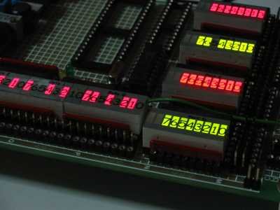
PIC microcontroller Programmer
(Completed in the year 2005)
My first own build programmer system. Spent quite a lot of time designing and fabricating the plastic box chassis. It works, but I never really work much with it after I brought myself a commercial version.
Microcontroller DIP IC Adaptor
(Completed in the year 2002-05-xx)
This is a interface board for fitting various model of PIC microcontroller to the programmer. The programming pins numer is different for every PIC microcontroller model. This interface board eliminate the need to build a new programmer board for different PIC microcontroller model.
PIC Programmer & Development board
(Completed in the year 2002-05-xx)
This board is design to be function as a multi purpose PIC microcontroller development board. I have build specially to trial run the microcontroller firmware I wrote. Bi-directional digital buffer are used, to protect the microcontroller from external device during interfacing. After working with microcontroller for some time, I find that this buffer interface is not necessary. Microcontroller I/O ports do not damage easily. When interfacing microcontroller with high powered or unknown devices, opto-coupler can be used instead. Opto-coupler provides maximum isolation as well as protection between the microcontroller and other devices.
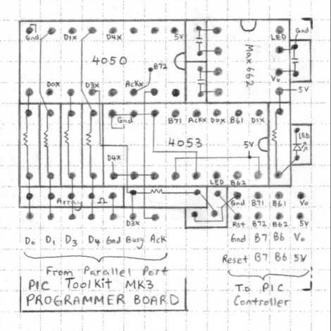
Attached to the main PCB is a smaller PCB board. It consist of a MAX232 converting computer RS232 to microcontroller TTL serial signal. This small board also include a charge pump circuit that generate 12V from a 5V source for the purpose of programming the PIC microcontroller. This programmer design “Toolkit TK3 PIC programmer” was taken reference from my favourite hobby magazine “Everyday Practical Electronics”.
(Completed in the year 2002-05-xx)
Input switches and Output LED test board interface. It is very useful when doing microcontroller project, because it can help to indicate if the firmware is running correctly inside the microcontroller. A must have kit when doing digital project.
PIC microcontroller selection references.
table updated in 26 May 2007
Number of Pin PIC16F series PIC18F series alternative
14 PIC16F688
18
(all models, not pin compatible)
PIC16F88, PIC16F648a, PIC16F628a, PIC16F84a PIC18F1320, PIC18F1220, PIC18F1330, PIC18F1230
28 PIC16F876a PIC18F2620, PIC18F2525, PIC18F2420
40 PIC16F877a PIC18F4620, PIC18F4525, PIC18F4420
40 USB supported Best features PIC18F4550
| Specification | ICSP pin out | Vcap pin out | OSC pin out | UART fixed pin out | Preferred I/O use | Comment | ||||||||||||||||
| Microcontroller part no. | Package /Pin no. | Volt | !MCLR | Vdd (+) | Vss (-) | PGD1 | PGC1 | PGD2 | PGC2 | PGD3 | PGC3 | Vcap | DisVreg | OSC1 | OSC2 | TX1 | RX1 | TX2 | RX2 | Input | Output | |
| 64 pins | ||||||||||||||||||||||
| PIC24HJ256GP206A | TQFP/64 | 3V – 3.6V | 7 | 10 19 26 38 57 | 9 20 25 41 | 18 | 17 | 47 | 48 | 16 | 15 | 56 | 39 | 40 | 33 | 34 | 32 | 31 | ||||
| 44 pins | ||||||||||||||||||||||
| PIC24FJ64GA004 | TQFP/44 | 2V – 3.6V | 18 | 17 28 40 | 16 29 39 | 21 | 22 | 8 | 9 | 41 | 42 | 7 | 6 | 30 | 31 | EEPROM | ||||||
| PIC24FJ64GA104 | TQFP/44 | 2V – 3.6V | 18 | 17 28 40 | 16 29 39 | 21 | 22 | 8 | 9 | 41 | 42 | 7 | 6 | 30 | 31 | |||||||
| PIC24FJ64GB004 | TQFP/44 | 2V – 3.6V | 18 | 17 28 40 | 16 29 39 | 21 | 22 | 8 | 9 | 19 | 20 | 7 | 6 | 30 | 31 | |||||||
| PIC24F32KA304 | TQFP/44 | 1.8V – 5.5V | 18 | 17 28 40 | 16 29 39 | 21 | 22 | 8 | 9 | 41 | 42 | 7 | 30 | 31 | 3 | 2 | 21 | 22 | ||||
| PIC24FJ32MC104 | TQFP/44 | 3V – 3.6V | 18 | 17 28 40 | 6 16 29 39 | 21 | 22 | 19 | 20 | 33 | 34 | 7 | 30 | 31 | ||||||||
| dsPIC30F2023 | TQFP/44 | 3V – 5.5V | 18 | 7 17 29 40 | 6 17 30 39 | 44 | 1 | 34 | 35 | 41 | 42 | 32 | 33 | 20 | 15 | 34 | 35 | |||||
| dsPIC33FJ128GP804 | TQFP/44 | 3V – 3.6V | 18 | 17 28 40 | 16 29 39 | 21 | 22 | 8 | 9 | 41 | 42 | 7 | 6 | 30 | 31 | No EEPROM | ||||||
| dsPIC33FJ32MC104 | TQFP/44 | 3V – 3.6V | ||||||||||||||||||||
| dsPIC33FJ128MC804 | TQFP/44 | 3V – 3.6V | 18 | 17 28 40 | 6 16 29 39 | 21 | 22 | 8 | 9 | 41 | 42 | 7 | 30 | 31 | ||||||||
| dsPIC33FJ16GS504 | TQFP/44 | 3V – 3.6V | 18 | 17 29 40 | 6 16 30 39 | 44 | 1 | 34 | 35 | 41 | 42 | 7 | 32 | 33 | ||||||||
| dsPIC33EP128GM304 | 8x input capture, 12x PWM, 4x UART, 3x SPI, 18x ADC | |||||||||||||||||||||
| Microcontroller part no. | Package /Pin no. | Volt | !MCLR | Vdd (+) | Vss (-) | PGD1 | PGC1 | PGD2 | PGC2 | PGD3 | PGC3 | Vcap | DisVreg | OSC1 | OSC2 | TX1 | RX1 | TX2 | RX2 | Input | Output | |
| 28 pins | ||||||||||||||||||||||
| PIC24F16KL402 | SOIC/28 | 1.8V – 3.6V | 1 | 13 28 | 8 27 | 4 | 5 | 21 | 22 | 14 | 15 | 9 | 10 | 16 | 6 | 4 | 5 | |||||
| PIC24F32KA302 | SOIC/28 | 1.8V – 5.5V | 1 | 13 28 | 8 27 | 4 | 5 | 21 | 22 | 14 | 15 | 9 | 10 | 16 | 6 | 4 | 5 | |||||
| PIC24FJ64GA002 | SOIC/28 | 2V – 3.6V | 1 | 13 28 | 8 27 | 4 | 5 | 21 | 22 | 14 | 15 | 20 | 19 | 9 | 10 | EEPROM | ||||||
| PIC24FJ64GA102 | SOIC/28 | 2V – 3.6V | 1 | 13 28 | 8 27 | 4 | 5 | 21 | 22 | 14 | 15 | 20 | 19 | 9 | 10 | |||||||
| PIC24FJ64GB002 | SOIC/28 | 2V – 3.6V | 1 | 13 28 | 8 27 | 4 | 5 | 21 | 22 | 20 | 19 | 9 | 10 | |||||||||
| PIC24FJ32MC102 | SOIC/28 | 3V – 3.6V | 1 | 13 28 | 19 27 | 4 | 5 | 2 | 3 | 11 | 12 | 20 | 9 | 10 | ||||||||
| dsPIC30F2010 | SOIC/28 | 2.5V – 5.5V | 1 | 13 20 28 | 8 19 27 | 17 | 18 | 9 | 10 | 17 | 18 | 11 | 12 | |||||||||
| dsPIC30F2020 | SOIC/28 | 3V – 5.5V | 1 | 13 20 28 | 8 19 27 | 17 | 18 | 11 | 12 | 14 | 15 | 9 | 10 | 17 | 18 | 11 | 12 | |||||
| dsPIC30F2012 | SOIC/28 | 2.5V – 5.5V | 1 | 13 20 28 | 8 19 27 | 17 | 18 | 9 | 10 | 17 | 18 | 11 | 12 | |||||||||
| dsPIC30F3010 | SOIC/28 | 2.5V – 5.5V | 1 | 13 20 28 | 8 19 27 | 17 | 18 | 9 | 10 | 17 | 18 | 11 | 12 | |||||||||
| dsPIC30F3013 | SOIC/28 | 2.5V – 5.5V | 1 | 13 20 28 | 8 19 27 | 17 | 18 | 9 | 10 | 17 | 18 | 21 11 | 22 12 | |||||||||
| dsPIC30F4012 | SOIC/28 | 2.5V – 5.5V | 1 | 13 20 28 | 8 19 27 | 17 | 18 | 9 | 10 | 17 | 18 | 11 | 12 | |||||||||
| dsPIC33FJ32GP102 | SOIC/28 | 3V – 3.6V | 1 | 13 28 | 8 19 27 | 4 | 5 | 2 | 3 | 11 | 12 | 20 | 9 | 10 | ||||||||
| dsPIC33FJ128GP802 | SOIC/28 | 3V – 3.6V | 1 | 13 28 | 8 19 27 | 4 | 5 | 21 | 22 | 14 | 15 | 20 | 9 | 10 | ||||||||
| dsPIC33FJ128MC802 | SOIC/28 | 3V – 3.6V | 1 | 13 28 | 8 19 27 | 4 | 5 | 21 | 22 | 14 | 15 | 20 | 9 | 10 | ||||||||
| dsPIC33FJ09GS302 | SOIC/28 | 3V – 3.6V | 1 | 13 28 | 8 19 27 | 17 | 18 | 11 | 12 | 14 | 15 | 20 | 9 | 10 | ||||||||
| dsPIC33FJ16GS502 | SOIC/28 | 3V – 3.6V | 1 | 13 28 | 8 19 27 | 17 | 18 | 11 | 12 | 14 | 15 | 20 | 9 | 10 | ||||||||
| Microcontroller part no. | Package /Pin no. | Volt | !MCLR | Vdd (+) | Vss (-) | PGD1 | PGC1 | PGD2 | PGC2 | PGD3 | PGC3 | Vcap | DisVreg | OSC1 | OSC2 | TX1 | RX1 | TX2 | RX2 | Input | Output | |
| 20pins | ||||||||||||||||||||||
| dsPIC33FJ12MC201 | Quite mature product. | |||||||||||||||||||||
| 18pins | ||||||||||||||||||||||
| dsPIC30F3012 | SOIC/18 | 2.5V – 5.5V | 1 | 14, 18 | 13, 17 | 11 | 12 | 6 | 7 | 11 | 12 | Mid number of I/O, operating at 5V. | ||||||||||
| 14pins | ||||||||||||||||||||||
| PIC24F04KA200 | TSSOP/14 | 1.8V – 3.6V | 1 | 14 | 13 | 3 | 2 | 6 | 7 | 4 | 5 | 11 | 12 | 10 | EEPROM Code Protection Warning!!!-> very very little memory, 4K only. Note enough for comfortable protocol processing. Please take note. | |||||||
| PIC24F08KL200 | 1.8V – 3.6V | 1 | 14 | 13 | 3 | 2 | 6 | 7 | 4 | 5 | 11 | 12 | 10 | Compatiable to PIC24F04KA200, with more memory. Face problem dealing with UART on its revision A0 | ||||||||
| 8 pins | ||||||||||||||||||||||
| PIC12F1840 | SOIC/8 | 1.8V – 5.5V | 4 | 1 | 8 | 7 | 6 | 2 | 3 | 7 | 6 | UART | ||||||||||
| PIC12F1822 | SOIC/8 | 1.8V – 5.5V | 4 | 1 | 8 | 7 | 6 | 2 | 3 | 7 | 6 | UART | ||||||||||
| PIC12HV615 | SOIC/8 | 2-15V | 4 | 1 | 8 | 7 | 6 | 2 | 3 | 2-15V | ||||||||||||
| PIC12F508 | SOIC/8 | 2-5.5V | 4 | 1 | 8 | 7 | 6 | 2 | 3 | low cost | ||||||||||||
| Microcontroller part no. | Package /Pin no. | Volt | !MCLR | Vdd (+) | Vss (-) | PGD1 | PGC1 | PGD2 | PGC2 | PGD3 | PGC3 | Vcap | DisVreg | OSC1 | OSC2 | TX1 | RX1 | TX2 | RX2 | Input | Output | |
| 6 pins | ||||||||||||||||||||||
| PIC10F322 | SOT23/6 | 1.8V – 5.5V | 6 | 5 | 2 | 1 | 3 | 3 | 4, 6 | 1, 3 | most powerful | |||||||||||
| PIC10F200 | SOT23/6 | 2V – 5.5V | 6 | 5 | 2 | 1 | 3 | 4, 6 | 1, 3 | low cost | ||||||||||||
Legend
Product Identification System (example)
dsPIC 33 FJ 16 MC1 02 T E / SP – XXX
—– — — — — — – – — —
1 2 3 4 5 6 7 8 9 10
1 – Microchip Trademark
2 – Architecture
10 –
12 –
16 –
18 –
24 – 16-bit Microcontroller
30 –
33 – 16-bit Digital Signal Controller
3 – Flash Memory Family
FJ – Flash program memory, 3.3V
F – Flash
EP – Enhanced Performance
HJ – Flash program memory, 3.3V, High-speed
4 – Program Memory Size (Kbyte)
5 – Product Group
GP? – General Purpose family
MC1 – Motor Control family
GS? – Switch Mode Power Supply (SMPS) family
6 – Pin Count
01 – 18-pin and 20-pin
02 – 28-pin and 32-pin
04 – 44-pin
06 – 64-pin
10 – 100-pin
7 – Tape and Reel Flag
– Standard packaging (tube or tray)
T – Tape and Reel
8 – Temperature Range
I – -40ºC to +85ºC (Industrial)
E – -40ºC to +125ºC (Extended)
H – -40ºC to +150ºC (High)
9 – Package
P – PDIP (Plastic Dual In-Line)
SS – SSOP (Plastic Shrink Small Outline)
SP – SPDIP (Shinny Plastic Dual In-Line)
SO – SOIC (Plastic Small Outline)
SN – SOIC (8-Lead)
SL – SOIC
ML – QFN (Plastic Quad, No Lead)
MR – QFN (Thin Quad Flatpack)
MG – QFN (Micro Lead Frame)
MM – QFN-S (Plastic Quad, No Lead)
MV – UQFN
PT – TQFP (Plastic Thin Quad Flatpack)
PF – TQFP (Plastic Thin Quad Flatpack, 14x14mm)
ST – TSSOP
TL – VTLA (Very Thin Leadless Array)
MF – Micro Lead Frame (DFN)
MC – DFN
OT – SOT-23
10- Pattern
QTP, SQTP, Code or Special Requirements
It is a headache trying to maximise the pin compatibility with a wider range of microcontrollers and applications,
such that firmware changes can be minimised.
The following are suggesting pins use for reference, base on the following microcontroller:
| Microcontroller part no. | Package /Pin no. | Volt | !MCLR | Vdd (+) | Vss (-) | PGD | PGC | OSC1 | OSC2 | TX1 | RX1 | TX1 Ctrl | TX2 | RX2 | TX2 Ctrl | Output Indicators | Input Switch | Input Analog | I/O | PWM | ||||
| 44 pins | ||||||||||||||||||||||||
| PIC24FJ64GA002 | TQFP/44 | 2V – 3.6V | 18 | 17 28 40 | 16 29 39 | 21 | 22 | 30 | 31 | 44 | 1 | 3 | 8 | 9 | 10 | 33, 34, 41 | 21, 22 | 19,20 | 15, 14, 11, 10 | |||||
| PIC24FJ64GA002 | SOIC/28 | 2V – 3.6V | 1 | 13 28 | 8 27 | 4 | 5 | 9 | 10 | 17 | 18 | 16 | 21 11 | 22 12 | 23 | 11, 12, 14 | 4, 5 | 2,3 | 26, 25, 24, 23 | |||||
| PIC12F1840 | 4 | 1 | 8 | 7 | 6 | 2 | 3 | 7 | 6 | 7, 6 | 4, 7, 6 | 3, 5 | ||||||||||||
| PIC10F322 | 6 | 5 | 2 | 1 | 3 | 1, 3 | 6, 1, 3 | 1, 3, 4 | 4 | 1, 3 |
PIC10F206 Microcontroller Schematic
source code:
2011-11-30 mini RGB microcontroller (c).zip
2011-11-30 mini RGB microcontroller (asm).zip
| Microchip MPLAB microcontroller startup troubleshooting guide.2009-10-08Getting my “hello world” firmware loaded into my new hardware design pose the most difficult part of the process. Time consuming doing debugging, and it can takes from half a day to two. The most difficult part, to spent those precious engineering time in debugging. Debugging what I thought I should be good in since I have done so many microcontroller project. Till this day, I still have the problem every time I start microcontroller project after a few months break. The reason I have this guide written. To provide myself possible solution, that can help me, if I encounter the same issue again.
| |
| Setting up the environment for project using MPLAB v8.701) Create a project folder. Open the MPLAB IDE software. 2) Open a new Project. Project>New… and enter in a name for the project. 3) Select the microcontroller that is use in the project. Configure>Select Device… and select the microcontroller for your project. 4) Check the configuration mode ‘Release’. Project>Build Configuration>Release 5) Select the correct toolsuite for your project. Project>Select Language Toolsuite… for typical C lanaguage implementation, choose “MPLAB” C30 C Complier (pic-30-gcc.exe) v3.24 6) Add in the search path for your microcontroller’s header file. Project>Build Options…>Project>Directories>Include Search Path, choose add to add in the directory that contains the microcontroller’s header files. For my example, the header is located in the directory “C:\Program Files (x86)\Microchip\MPLAB C30\support\dsPIC33F\h” 7) Add in or create all the *.c & *.h files, to start your programming.
| |
| I use PICkit2 most of the time, because it is a small and compact programmer. Today, I tried out PICkit3. Well I am quite impress with the changes from PICkit2. I hope to get that one day. As for this article, the error messages is meant for PICkit2 use on the IDE Mplab version 8.36.I do not have much problem doing the compilation of my C programs. The frustration comes during the loading of my hex codes into my newly design prototype circuit. Most of the time is due to human error, because my prototype board are mainly hand soldered, pin by pin.On the left is the typical error message I encounter. I am scare of them to be frank. I see them almost every time.
| Initialisation of PICkit2 when connected to MplabInitializing PICkit 2 version 0.0.3.63 Found PICkit 2 – Operating System Version 2.32.0 Target power not detected – Powering from PICkit 2 ( 3.30V) PKWarn0003: Unexpected device ID: Please verify that a PIC24FJ32GA004 is correctly installed in the application. (Expected ID = 0x44D0000, ID Read = 0x0) PICkit 2 Ready |
| Every time when I press the shortcut key Alt+G, G to program the controller, PICkit will attempt to read the device ID of the microcontroller. The microcontroller used in this example is PIC24FJ32GA004.As you can see in the error on the right. PICkit is expecting the microcontroller with device ID 0x44D0000. The read by PICkit detects a ID of 0x0. In fact this same error is identical as if the PICkit programmer is not inserted to the ICSP programming pins at all.This is a hard evident that the microcontroller is not wired properly or evenly not wired at all.
| Error Encounter using PICkit2 version 2.63, MPLAB version 8.36Programming Target (10/8/2009 4:37:06 PM) PKWarn0003: Unexpected device ID: Please verify that a PIC24FJ32GA004 is correctly installed in the application. (Expected ID = 0x44D0000, ID Read = 0x0) Erasing Target Programming Program Memory (0x0 – 0x23FF) PE Error: Using ICSP Verifying Program Memory (0x0 – 0x23FF) PE Error: Using ICSP PK2Error0027: Failed verify (Address = 0x0 – Expected Value 0x40200 – Value Read 0x0) PICkit 2 Ready |
 1) The first thing to check if your hardware. It is most of the time the source of the problem. Check if the ICSP programming pins are wired correctly
ICSP pin out
Pin 1: !MCLR
Pin 2: Vdd (3.3V or 5V, depends on the device)
Pin 3: Vss (ground)
Pin 4: PGD (data line)
Pin 5: PGC (clocking line)
Pin 6: unused
Attached on the left is the basic schematic of the microcontroller PIC24FJ32GA004 if your wiring is exactly the same as what is shown, PICkit2 should be able to load the hex file into your controller without any problem.
An advise to you, don’t assume that your wiring is correct. Check 2 or more times to ensure. This is often one of my major mistake make. The schematic is typically correct, but because of the confident doing many similar project, the checking is often the lacking part.
For PIC24FJ series controller, there is a pin Vcap & DISVREG. Make sure that there is the capacitor there. !MCLR pin to be pull up to Vdd using a resistor about 10kohm.
For more detail: Introducing PIC Microcontroller projects