The communication protocol is explained as follows. The MCU (microcontroller unit) first sends a low signal of width 18mS to the DHT11. After this signal, the MCU pulls up the communication line and waits for the response from DHT11. It make take up to 2. to 40uS. Then the DHT11 pulls down the communication line and keeps it low for 80uS.
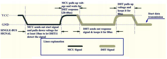
Then DHT11 pulls up the line and keeps it high for 80uS. Then the DHT pulls down the line for 50uS and the next high pulse will be the first bit of the data. The data is send in bursts of 8 bits. Each high pulse of the burst indicates a data signal. The 50uS low signals between the data bits are just spacers. The logic of the data bit is identified by measuring the width of it. A 26 to 28uS wide pulse indicates a “LOW” and 70uS wide pulse indicates a “HIGH”. In simple words, an pulse narrower than 50uS can be taken as a “LOW” and wider than 50us can be taken as a “HIGH”. The first 8 bits of the data burst represents the integral value of the relative humidity, second 8 bits represent the decimal value of the relative humidity, third 8 bits represent the integral value of the temperature data, and the last 8 bits represent the decimal value of the temperature data, For DHT11 the decimal values are always zero and we are
For more detail: Humidity sensor using 8051